Step 14. Hierarchical OSPF topology and summary LSA
Goals
The goal of this step is to demonstrate hierarchical OSPF with multiple areas and to examine how Area Border Routers (ABRs) generate and flood Summary LSAs to provide inter-area reachability.
OSPF uses a hierarchical design to improve scalability. The network is divided into areas, with Area 0 (the backbone area) connecting all other areas. Routers with interfaces in multiple areas are called ABRs. ABRs generate Summary LSAs (Type-3 LSAs) to advertise networks from one area into another area, allowing routers to learn about networks outside their own area without needing to know the detailed topology of other areas.
Configuration
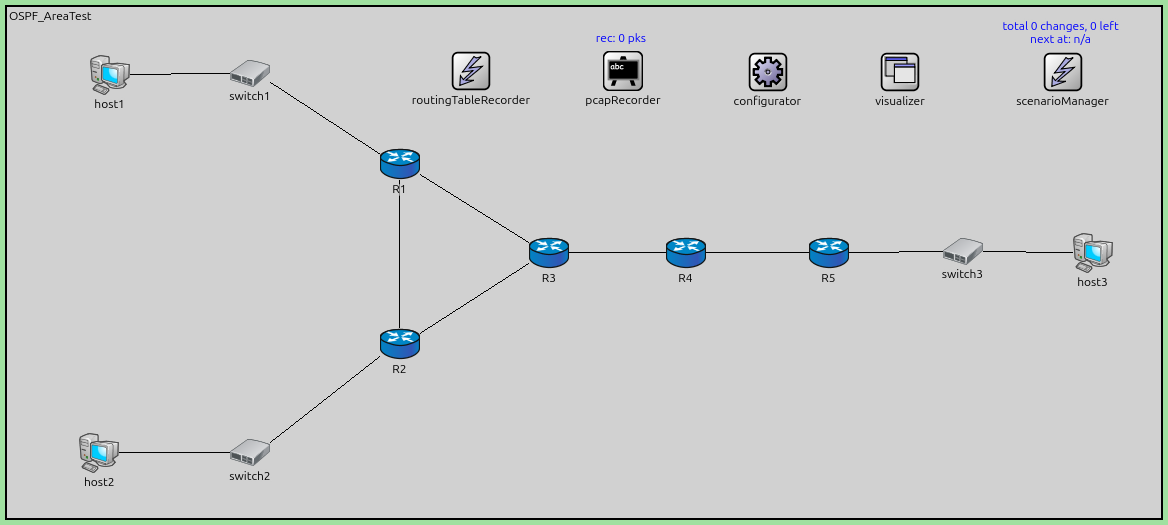
This step uses the OSPF_AreaTest network with three OSPF areas:
Area 0.0.0.0 (backbone): Contains the link between R3 and R4
Area 0.0.0.1: Contains R1, R2, R3, host1, and host2
Area 0.0.0.2: Contains R4, R5, and host3
R3 and R4 are ABRs because they have interfaces in multiple areas.
network OSPF_AreaTest
{
    @display("bgb=1153.1,510.9");

    types:
        channel PppLink100M extends DatarateChannel
        {
            delay = 5us;
            datarate = 100Mbps;
        }

    submodules:
        configurator: Ipv4NetworkConfigurator {
            @display("p=760.5,65");
        }
        visualizer: IntegratedCanvasVisualizer {
            @display("p=893.1,65");
        }
        routingTableRecorder: RoutingTableRecorder {
            @display("p=464,64");
        }
        pcapRecorder: PcapRecorder {
            @display("p=616,64");
        }
        scenarioManager: ScenarioManager {
            @display("p=1055.6,65");
        }
        host1: StandardHost {
            @display("p=102.7,67.6");
        }
        host2: StandardHost {
            @display("p=92.299995,445.9");
        }
        R1: Router {
            @display("p=392.6,157.3");
        }
        R2: Router {
            @display("p=392.6,336.69998");
        }
        R3: Router {
            @display("p=542.1,245.7");
        }
        switch1: EthernetSwitch {
            @display("p=243.09999,66.299995");
        }
        switch2: EthernetSwitch {
            @display("p=243.09999,445.9");
        }
        host3: StandardHost {
            @display("p=1085.5,245.7");
        }
        R4: Router {
            @display("p=678.6,245.7");
        }
        R5: Router {
            @display("p=821.6,245.7");
        }
        switch3: EthernetSwitch {
            @display("p=955.5,244.4");
        }

    connections:
        host1.ethg++ <--> Eth100M <--> switch1.ethg++;
        switch1.ethg++ <--> Eth100M <--> R1.ethg++;
        R1.pppg++ <--> PppLink100M <--> R3.pppg++;
        switch2.ethg++ <--> Eth100M <--> host2.ethg++;
        R1.pppg++ <--> PppLink100M <--> R2.pppg++;
        R2.pppg++ <--> PppLink100M <--> R3.pppg++;
        R2.ethg++ <--> Eth100M <--> switch2.ethg++;
        R4.pppg++ <--> PppLink100M <--> R5.pppg++;
        R5.ethg++ <--> Eth100M <--> switch3.ethg++;
        switch3.ethg++ <--> Eth100M <--> host3.ethg++;
        R3.pppg++ <--> PppLink100M <--> R4.pppg++;
}
The configuration in omnetpp.ini is the following:
[Config Step14]
description = "Hierarchical OSPF topology and summary LSA"
network = OSPF_AreaTest

*.configurator.config = xml("<config> \
                                <interface hosts='R3' towards='R4' address='192.168.0.x' netmask='255.255.255.x' /> \
                                <interface hosts='R4' towards='R3' address='192.168.0.x' netmask='255.255.255.x' /> \
                                \
                                <interface among='host1 host2 R1 R2 R3' address='192.168.11.x' netmask='255.255.255.x' /> \
                                <interface among='R3 R4 R5 host3' address='192.168.22.x' netmask='255.255.255.x' /> \
                                \
                                <route hosts='host*' destination='*' netmask='0.0.0.0' interface='eth0' /> \
                             </config>")

*.R*.ospf.ospfConfig = xmldoc("ASConfig_Area.xml")

*.visualizer.routingTableVisualizer.displayRoutingTables = true
*.visualizer.routingTableVisualizer.destinationFilter = "R*"
*.visualizer.routingTableVisualizer.nodeFilter = "R*"

# application parameters
*.host1.numApps = 1
*.host1.app[0].typename = "PingApp"
*.host1.app[0].destAddr = "host3"
*.host1.app[0].startTime = 60s
The OSPF configuration in ASConfig_Area.xml assigns interfaces to areas:
<?xml version="1.0"?>
<OSPFASConfig xmlns:xsi="http://www.w3.org/2001/XMLSchema-instance" xsi:schemaLocation="OSPF.xsd">

  <!-- Areas -->
  <Area id="0.0.0.0">
    <AddressRange address="R3>R4" mask="R3>R4" />
    <AddressRange address="R4>R3" mask="R4>R3" />
  </Area>

  <Area id="0.0.0.1">
    <AddressRange address="R1>switch1" mask="R1>switch1" />
    <AddressRange address="R1>R2" mask="R1>R2" />
    <AddressRange address="R1>R3" mask="R1>R3" />

    <AddressRange address="R2>switch2" mask="R2>switch2" />
    <AddressRange address="R2>R1" mask="R2>R1" />
    <AddressRange address="R2>R3" mask="R2>R3" />

    <AddressRange address="R3>R1" mask="R3>R1" />
    <AddressRange address="R3>R2" mask="R3>R2" />
  </Area>

  <Area id="0.0.0.2">
    <AddressRange address="R4>R5" mask="R4>R5" />

    <AddressRange address="R5>R4" mask="R5>R4" />
    <AddressRange address="R5>switch3" mask="R5>switch3" />
  </Area>

  <!-- Routers -->
  <Router name="R1" RFC1583Compatible="true">
    <BroadcastInterface ifName="eth0" areaID="0.0.0.1" interfaceMode="Passive" />
    <PointToPointInterface ifName="ppp0" areaID="0.0.0.1" />
    <PointToPointInterface ifName="ppp1" areaID="0.0.0.1" />
  </Router>

  <Router name="R2" RFC1583Compatible="true">
    <BroadcastInterface ifName="eth0" areaID="0.0.0.1" interfaceMode="Passive" />
    <PointToPointInterface ifName="ppp0" areaID="0.0.0.1" />
    <PointToPointInterface ifName="ppp1" areaID="0.0.0.1" />
  </Router>

  <Router name="R3" RFC1583Compatible="true">
    <PointToPointInterface ifName="ppp0" areaID="0.0.0.1" />
    <PointToPointInterface ifName="ppp1" areaID="0.0.0.1" />
    <PointToPointInterface ifName="ppp2" areaID="0.0.0.0" />
  </Router>

  <Router name="R4" RFC1583Compatible="true">
    <PointToPointInterface ifName="ppp0" areaID="0.0.0.2" />
    <PointToPointInterface ifName="ppp1" areaID="0.0.0.0" />
  </Router>

  <Router name="R5" RFC1583Compatible="true">
    <BroadcastInterface ifName="eth0" areaID="0.0.0.2" interfaceMode="Passive" />
    <PointToPointInterface ifName="ppp0" areaID="0.0.0.2" />
  </Router>

</OSPFASConfig>
Results
After OSPF convergence, the network exhibits the following behavior:
Intra-area routing: Within Area 0.0.0.1, routers R1, R2, and R3 exchange Router LSAs to build a complete view of the area topology. Similarly, R4 and R5 exchange Router LSAs within Area 0.0.0.2.
Summary LSA generation:
R3 (ABR between Area 0.0.0.1 and Area 0.0.0.0) generates Summary LSAs to advertise networks from Area 0.0.0.1 into Area 0.0.0.0, and vice versa. For example, R3 advertises the 192.168.11.x/30 networks into the backbone.
R4 (ABR between Area 0.0.0.2 and Area 0.0.0.0) generates Summary LSAs to advertise the 192.168.22.x/30 networks from Area 0.0.0.2 into Area 0.0.0.0.
Both ABRs then propagate Summary LSAs from the backbone into their respective non-backbone areas.
Inter-area routing: Routers use Summary LSAs to install inter-area routes in their routing tables. For example:
R1 learns about the 192.168.22.x networks via Summary LSAs from R3
R5 learns about the 192.168.11.x networks via Summary LSAs from R4
The routing table shows inter-area routes (learned via Summary LSAs) alongside intra-area routes.
Sources:
omnetpp.ini,
OSPF_AreaTest.ned,
ASConfig_Area.xml
Discussion
Use this page in the GitHub issue tracker for commenting on this tutorial.