Step 12. Changing to a more realistic radio model
Goals
After so many steps, we let go of the unit disk radio model and introduce a more realistic one. Our new radio will use an APSK modulation scheme, but still without other techniques like forward error correction, interleaving or spreading. We also want our model of the radio channel to simulate attenuation and obstacle loss.
The model
Switching to APSK radio
In this step, we replace GenericUnitDiskRadio with ApskScalarRadio. ApskScalarRadio models a radio with an APSK (amplitude and phase-shift keying) modulation scheme. By default it uses BPSK, but QPSK, QAM-16, QAM-64, QAM-256 and several other modulations can also be configured. (Modulation is a parameter of the radio’s transmitter component.)
Since we are moving away from the “unit disc radio” type of abstraction, we need to specify the carrier frequency, signal bandwidth and transmission power of the radios. Together with other parameters, they will allow the radio channel and the receiver models to compute path loss, SNIR, bit error rate, and other values, and ultimately determine the success of the reception.
ApskScalarRadio also adds realism in that it simulates that the data are preceded by a preamble and a physical layer header. Their lengths are also parameters (and may be set to zero when not needed.)
NOTE: When choosing the preamble and the physical layer header lengths,
we needed to take care that the ackTimeout parameter of
CsmaCaMac is still valid. (The preamble and the physical layer
header contribute to the duration of the ACK frame as well.)
Physical parameters of the receiver are important, too. We configure the following receiver parameters: - sensitivity [dBm]: if the signal power is below this threshold, reception is not possible (i.e. the receiver cannot go from the channel busy state to receiving) - energy detection threshold [dBm]: if reception power is below this threshold, no signal is detected and the channel is sensed to be empty (this is significant for the “carrier sense” part of CSMA) - SNIR threshold [dB]: reception is not successful if the SNIR is below this threshold
The concrete values in the inifile were chosen to approximately reproduce the communication and interference ranges used in the previous steps.
Setting up the wireless channel
Since we switched the radio to ApskScalarRadio, we also need to change the medium to ScalarRadioMedium. In general, one always needs to use a medium that is compatible with the given radio. (With GenericUnitDiskRadio, we also used UnitDiskRadioMedium.)
ScalarRadioMedium has “slots” to plug in various propagation models, path loss models, obstacle loss models, analog models, and background noise models. Here we make use of the fact that the default background noise model is homogeneous isotropic white noise, and set up the noise level to a nonzero value (-90dBm).
Configuration:
[Config Wireless12]
description = Changing to a more realistic radio model
extends = Wireless11

*.radioMedium.signalAnalogRepresentation = "scalar"
*.radioMedium.backgroundNoise.power = -90dBm
*.radioMedium.mediumLimitCache.centerFrequency = 2GHz

*.host*.wlan[0].radio.typename = "ApskRadio"
*.host*.wlan[0].radio.signalAnalogRepresentation = "scalar"
*.host*.wlan[0].radio.centerFrequency = 2GHz
*.host*.wlan[0].radio.bandwidth = 2MHz
*.host*.wlan[0].radio.transmitter.power = 1.4mW
*.host*.wlan[0].radio.transmitter.preambleDuration = 10us
*.host*.wlan[0].radio.transmitter.headerLength = 8B
*.host*.wlan[0].radio.receiver.sensitivity = -85dBm
*.host*.wlan[0].radio.receiver.energyDetection = -85dBm
*.host*.wlan[0].radio.receiver.snirThreshold = 4dB

*.hostR1.wlan[*].radio.bitErrorRate.result-recording-modes = default,+vector
Results
What happens is about the same as in the previous step. At first, host A’s packets are relayed by host R2 until it moves so that the wall separates them. The connection is re-established when host R1 moves out from behind the wall. Then it gets out of communication range, and the new route goes through hosts R2 and R3.
In this model, more physical effects are simulated than in previous steps. There are radio signal attenuation, background noise and a more realistic radio model. The blue circles representing the communication range is an approximation. There is no distinct distance where receptions fail, as in the case of GenericUnitDiskRadio.
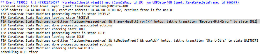
In host A, the MAC receives the packet UDPData-408 from the radio. The MAC drops the packet because of bit errors; this can be seen in the following log:
Number of packets received by host B: 665
Sources: omnetpp.ini,
WirelessC.ned
Discussion
Use this page in the GitHub issue tracker for commenting on this tutorial.