PCAP Recording
Goals
INET has the capability to record PCAP traces from simulations. These PCAP files have the same format as real-world PCAP traces, so that the same tools and techniques used to analyze real traffic can also be applied to simulated traffic. This means that popular tools like Wireshark and tcpdump can be leveraged in the context of simulations.
This demonstration includes a sample simulation that generates and records PCAP traces of TCP, UDP, and ICMP traffic, using various physical layer protocols such as Ethernet and 802.11.
4.6The model
To record PCAP traces in a node, a PcapRecorder module
needs to be included in it. Pcap recorder modules can be easily included
in hosts and routers by specifying their numPcapRecorders parameter
(available in modules that extend LinkLayerNodeBase, such as
StandardHost and derivatives, and router modules.)
The PCAP recorder module records packets sent to and from modules that
are in the same host as the PCAP recorder module. It writes traces in a
PCAP file, which has to be specified by the pcapFile parameter.
This parameter acts as the main switch for recording, thus specifying
this parameter enables packet capture. The PCAP recorder can write traces
in the original or the next-generation PCAP file format, selected by the
fileFormat parameter (pcap or pcapng).
The moduleNamePatterns parameter specifies which modules’ traffic
should be recorded. It takes a space separated list of module names. For
selecting a module vector, [*] can be used. The recorded modules are
on the same level in the hierarchy as the PCAP recorder module. The
default value for the moduleNamePatterns parameter is
wlan[*] eth[*] ppp[*], so it records the most commonly
present L2 interfaces. The dumpProtocols parameter is a filter and
selects which protocols to include in the capture. It matches packets
which are of the specified protocol type at the level of capture, but
not the protocol type of encapsulated packets. The parameter takes
protocol names registered in INET (see
/inet/src/inet/common/Protocol.cc)
The parameter’s default value is "ethernetmac ppp ieee80211mac".
By default, the PCAP recorder module records L2 frames, but setting the
moduleNamePatterns to ipv4, for example, lets one record L3
frames (note that the parameter’s value is lowercase because it refers
to the actual ipv4 module in the host, not the module type.)
Additionally, the packetFilter parameter can use an expression
to filter packets. The expression is evaluated for all packets to
a boolean value indicating a match. The expression can contain the packet’s
fields (such as its name), contained chunks and their fields, protocol
headers, etc. The default value is * that matches all packets,
thus no packets are filtered. For more information on the packet filter,
refer to the Recording PCAP Traces section in the INET User’s Guide.
To summarize: the moduleNamePatterns parameter specifies which
modules’ outputs should be captured. The
dumpProtocols parameter can narrow the set of recorded protocols at
the level of capture. The packetFilter parameter can further
narrow the set of captured packets.
The configuration
The example simulation for this showcase contains wired hosts, wireless
hosts, and routers. The hosts are configured to generate TCP, UDP and
ICMP traffic. The hosts connect to routers via Ethernet; the connection
between the routers is PPP. The wireless hosts communicate via 802.11.
The simulation can be run by choosing the PcapRecording
configuration from the ini file. The simulation uses the following
network:
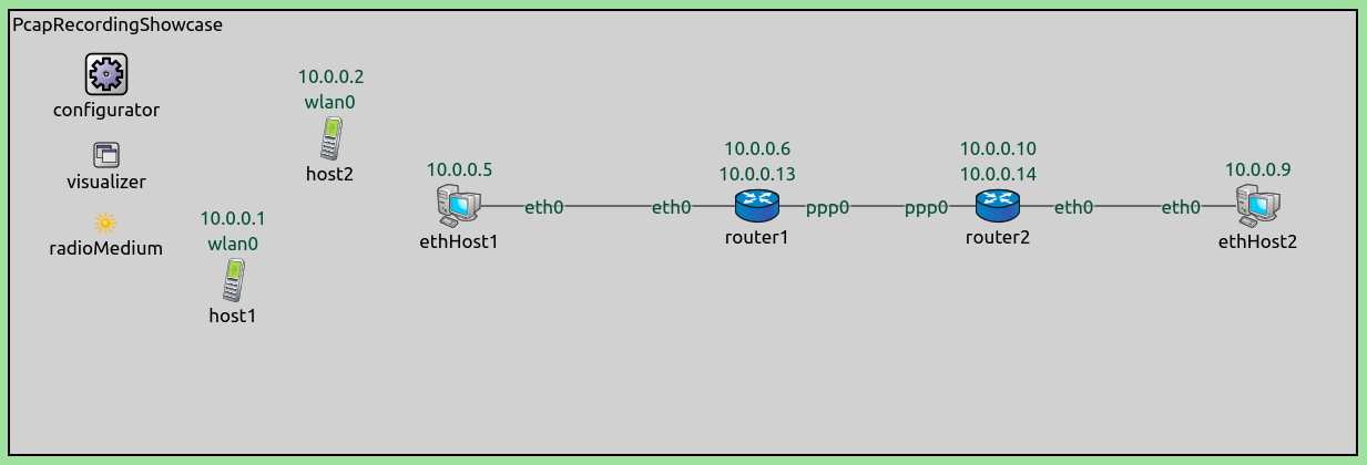
The network contains two adhocHosts named host1 and host2,
and two StandardHosts named ethHost1 and ethHost2. There
are two Router modules (router1 and router2), which are
connected by PPP. Each wired host is connected to one of
the routers via Ethernet. The network also contains an
Ipv4NetworkConfigurator, an Ieee80211RadioMedium, and an
IntegratedMultiCanvasVisualizer module.
Traffic generation is set up the following way: host1 is configured
to send a UDP stream to host2 (via 802.11), ethHost1 is
configured to open a TCP connection to ethHost2, and send a 1Mbyte
file (via Ethernet). Additionally, ethHost1 is configured to ping
ethHost2.
We set up multiple PCAP recorder modules in various hosts in the network:
In host1, we’ll record 802.11 traffic on the wlan0 interface:
*.host1.numPcapRecorders = 1
*.host1.pcapRecorder[0].pcapFile = "${resultdir}/host1.80211.pcap"
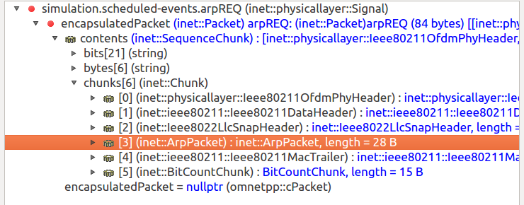
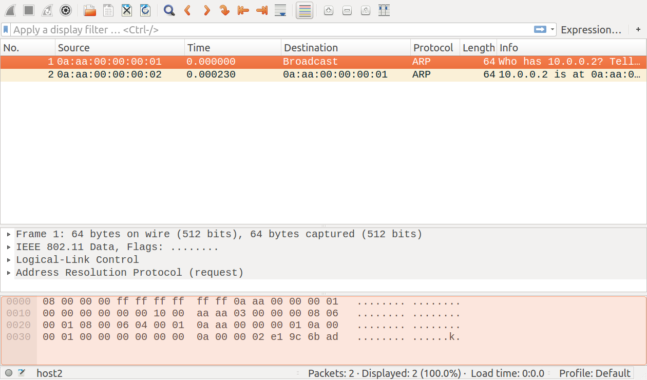
In host2, we’ll record only the ARP packets from the 802.11 traffic
on wlan0. The
packetFilter is set to record only packets of ArpPacket
class:
*.host2.numPcapRecorders = 1
*.host2.pcapRecorder[0].pcapFile = "${resultdir}/host2.arp.pcap"
*.host2.pcapRecorder[0].packetFilter = expr(has(ArpPacket))
The packetFilter parameter’s value *ArpPacket matches the
inet::ArpPacket class. There is an ARP request packet open in the
packet inspector on the following image:
In ethHost1, we’ll record Ethernet traffic on the eth0
interface:
*.ethHost1.numPcapRecorders = 1
*.ethHost1.pcapRecorder[0].pcapFile = "${resultdir}/ethHost1.eth.pcap"
There are two PCAP recorder modules in router1, with one of them
recording Ethernet traffic on eth0 and the other PPP traffic on
ppp0. The moduleNamePatterns parameter needs to be set for both
PCAP recorder modules, because router1 has two interfaces.
*.router1.numPcapRecorders = 2
*.router1.pcapRecorder[0].pcapFile = "${resultdir}/router1.ppp.pcap"
*.router1.pcapRecorder[0].moduleNamePatterns = "ppp[0]"
*.router1.pcapRecorder[1].pcapFile = "${resultdir}/router1.eth.pcap"
*.router1.pcapRecorder[1].moduleNamePatterns = "eth[0]"
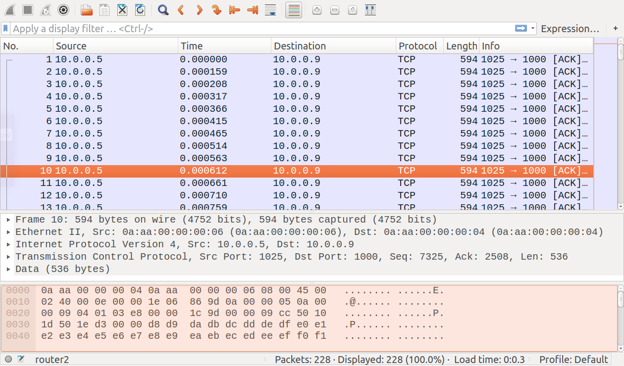
In router2, we’ll record only packets carrying TCP data on the eth0
interface. router2 has two interfaces, so the moduleNamePatterns
parameter needs to be set. The packet data filter is set to match packets
containing a TcpHeader and an Ipv4Header, and where the TCP payload
length is greater than 0 (so that ACKs and handshake packets are not recorded).
TCP packets don’t have a payload length field, so need to calculate the payload length as follows:
IPv4 total length field - IPv4 header length field - TCP header header length field
Here is the ini configuration:
*.router2.numPcapRecorders = 1
*.router2.pcapRecorder[0].moduleNamePatterns = "eth[0]"
*.router2.pcapRecorder[0].pcapFile = "${resultdir}/router2.tcpdata.pcap"
*.router2.pcapRecorder[0].packetFilter = expr(has(TcpHeader) && has(Ipv4Header) && Ipv4Header.totalLengthField-Ipv4Header.headerLength-TcpHeader.headerLength > 0B)
In ethHost2, we’ll only record IPv4 frames, without network layer protocol information. The
dumpProtocols parameter’s default is
ethernetmac ppp ieee80211mac, so it has to be set to ipv4.
*.ethHost2.numPcapRecorders = 1
*.ethHost2.pcapRecorder[0].pcapFile = "${resultdir}/ethHost2.ip.pcap"
*.ethHost2.pcapRecorder[0].dumpProtocols = "ipv4"
By default, modules like Ipv4 and EthernetInterface don’t compute checksum and FCS fields, but assume they are correct (“declared correct” mode). To record PCAP traces with correctly calculated checksum and FCS values, the L2 and L3 modules need to be set to compute them:
**.checksumMode = "computed"
**.fcsMode = "computed"
Note that these settings are required, otherwise an error is returned.
The alwaysFlush parameter controls whether to write packets to the
PCAP file as they are recorded or after the simulation has concluded.
It is false by default, but it’s set to true in all PCAP
recorders to make sure there are recorded packets even if the simulation
crashes:
**.pcapRecorder[*].alwaysFlush = true
Results
The following video shows the traffic in the network:
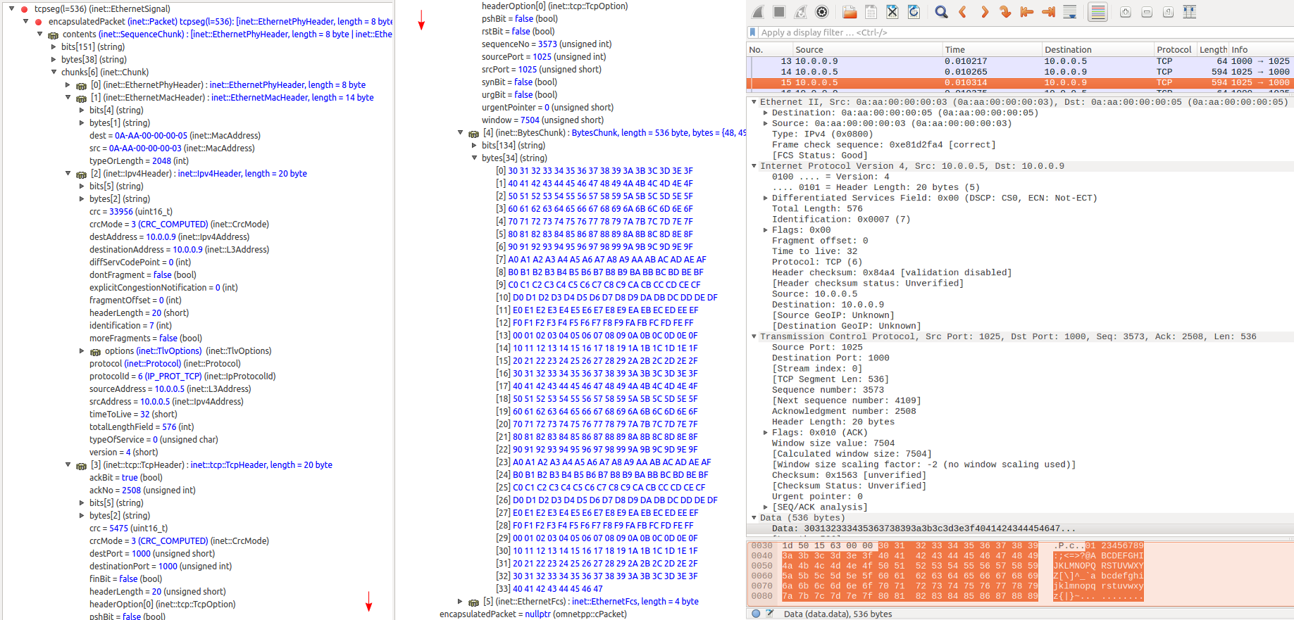
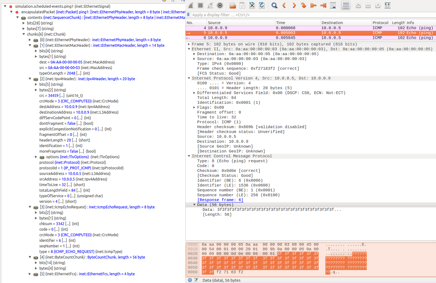
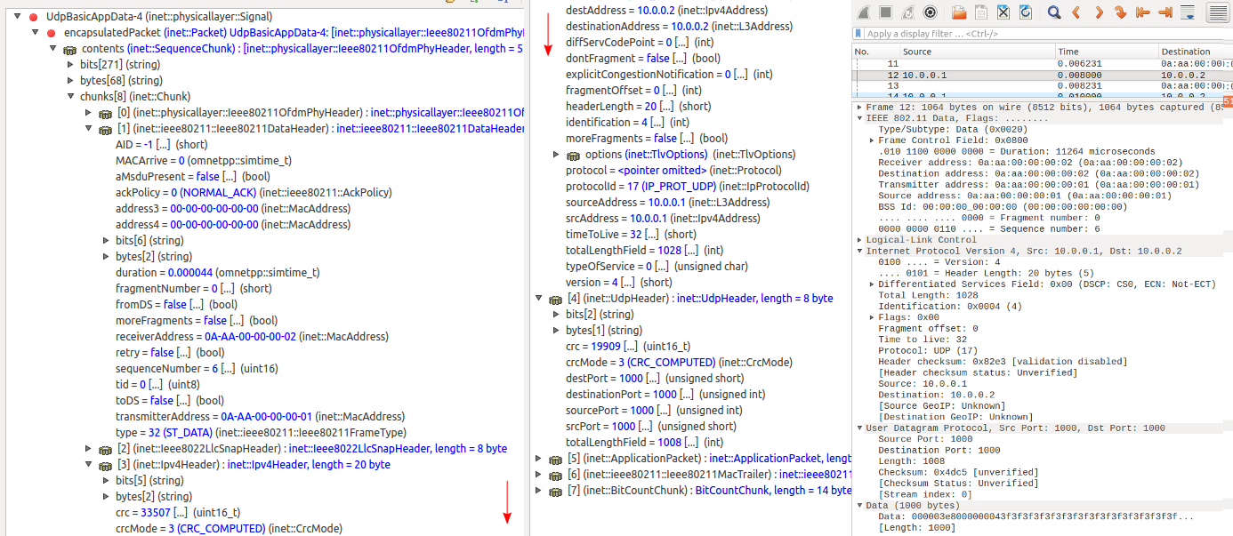
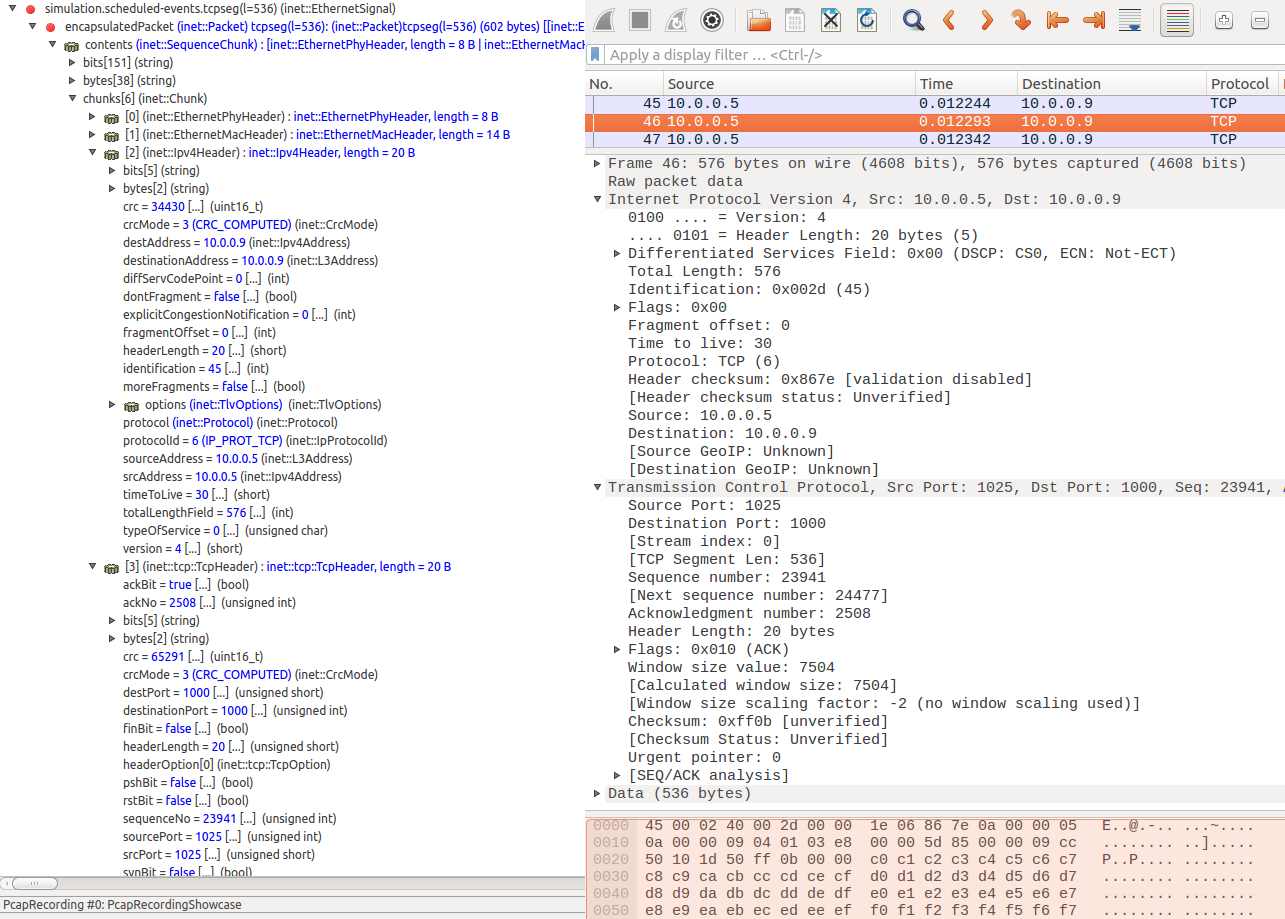
The following images show the same packets viewed in Qtenv’s packet mode inspector panel and the PCAP trace opened with Wireshark. Both display the same data about the same packet (with the same data, sequence number, FCS, etc. Click to zoom.)
TCP data, in ethHost1 (sent from ethHost1 to ethHost2):
Ping request, in router1’s eth interface (sent from ethHost1 to
router1):
TCP ACK, in router1’s ppp interface (sent from ethHost1 to
ethHost2):

UDP data packet, in host1’s wlan interface (sent from host1 to
host2):
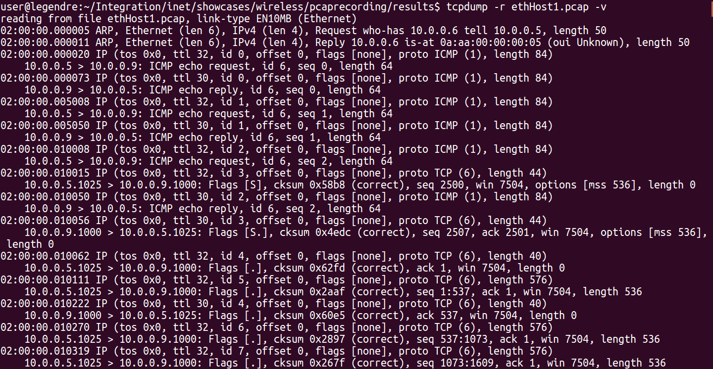
The following screenshot shows ethHost1.pcap opened with TCPDump:
TCP data packet, in ethHost2, recorded at the IPv4 module (sent from
ethHost1 to ethHost2):
The following images are the PCAP traces from host2 and router2,
where the set of recorded packets were narrowed with
packetFilter.
The ARP packets from host2:
The TCP data packets from router2:
Sources: omnetpp.ini, PcapRecordingShowcase.ned
Try It Yourself
If you already have INET and OMNeT++ installed, start the IDE by typing
omnetpp, import the INET project into the IDE, then navigate to the
inet/showcases/general/pcaprecording folder in the Project Explorer. There, you can view
and edit the showcase files, run simulations, and analyze results.
Otherwise, there is an easy way to install INET and OMNeT++ using opp_env, and run the simulation interactively.
Ensure that opp_env is installed on your system, then execute:
$ opp_env run inet-4.6 --init -w inet-workspace --install --build-modes=release --chdir \
   -c 'cd inet-4.6.*/showcases/general/pcaprecording && inet'
This command creates an inet-workspace directory, installs the appropriate
versions of INET and OMNeT++ within it, and launches the inet command in the
showcase directory for interactive simulation.
Alternatively, for a more hands-on experience, you can first set up the workspace and then open an interactive shell:
$ opp_env install --init -w inet-workspace --build-modes=release inet-4.6
$ cd inet-workspace
$ opp_env shell
Inside the shell, start the IDE by typing omnetpp, import the INET project,
then start exploring.
Discussion
Use this page in the GitHub issue tracker for commenting on this showcase.