Automatic Stream Configuration with Failure Protection
Goals
In this showcase, we demonstrate INET’s automatic FRER configuration capabilities. Using automatic configurators that compute redundant paths based on specified failure protection requirements, we compare network behavior with and without frame replication during a controlled node failure, showing how FRER maintains 100% packet delivery even during equipment outages.
4.6Frame Replication and Elimination
Frame Replication and Elimination for Reliability (FRER) is a mechanism standardized in IEEE 802.1CB that provides seamless redundancy for time-sensitive networking applications. The core idea is to protect critical data streams against link failures and packet loss by:
Replicating frames: At strategic points in the network, frames from a stream are duplicated and sent along multiple disjoint paths toward the destination.
Eliminating duplicates: At merge points and at the destination, duplicate frames are identified (using sequence numbers) and eliminated, ensuring that only one copy of each frame is delivered to the application.
For more information about FRER, read the corresponding section in the INET User’s Guide.
The Model
In this case, we use an automatic failure protection configurator that takes the link and node failure protection requirements for each redundant stream as an argument. The automatic configurator computes the different paths that each stream must take in order to be protected against any of the listed failures so that at least one working path remains.
The simulation demonstrates a controlled failure scenario:
At
t=20ms, switchs2acrashes and becomes unavailableAt
t=80ms, switchs2arecovers and becomes operational again
We run two configurations to compare the behavior:
NoFrameReplication: Standard operation without frame replication, demonstrating single point of failure
FrameReplication: Frame replication enabled with automatic configuration for failure protection
Here is the network:
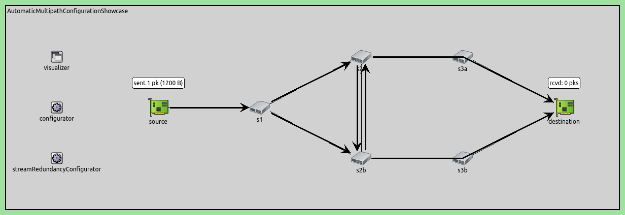
The network topology provides four distinct paths from source to destination:
Upper path: source → s1 → s2a → s3a → destination
Lower path: source → s1 → s2b → s3b → destination
Downward zig-zag path: source → s1 → s2a → s2b → s3b → destination
Upward zig-zag path: source → s1 → s2b → s2a → s3a → destination
The zig-zag paths utilize the cross-connection between s2a and s2b, allowing frames to switch between the upper and lower branches.
Configuration
Application Configuration
The source generates UDP traffic at a constant rate:
*.source.numApps = 1
*.source.app[0].typename = "UdpSourceApp"
*.source.app[0].io.destAddress = "destination"
*.source.app[0].io.destPort = 1000
*.source.app[0].source.displayStringTextFormat = "sent %p pk (%l)"
*.source.app[0].source.packetLength = 1200B
*.source.app[0].source.productionInterval = 1ms
The source sends 1200-byte UDP packets every 1ms (100 packets during the 100ms simulation). The destination simply receives and counts the packets:
*.destination.numApps = 1
*.destination.app[0].typename = "UdpSinkApp"
*.destination.app[0].io.localPort = 1000
Failure Scenario
The ScenarioManager creates a deterministic node failure:
*.scenarioManager.script = xml("<script>\
                                  <at t='20ms'><crash module='s2a'/></at> \
                                  <at t='80ms'><startup module='s2a'/></at> \
                                </script>")
Switch s2a crashes at 20ms and recovers at 80ms, creating a 60ms outage window to test frame replication effectiveness.
Frame Replication Configuration (FrameReplication configuration only)
*.*.hasStreamRedundancy = true
This enables IEEE 802.1CB frame replication and elimination functionality at all nodes.
Automatic Configurators (FrameReplication configuration only)
Two configurators work together to set up the redundant paths:
*.streamRedundancyConfigurator.typename = "StreamRedundancyConfigurator"
*.failureProtectionConfigurator.typename = "FailureProtectionConfigurator"
The FailureProtectionConfigurator analyzes network topology and failure requirements to compute redundant paths. The StreamRedundancyConfigurator then configures the replication and elimination points based on these computed paths.
MAC Configuration Requirements (FrameReplication configuration only)
Two special MAC-related settings are required:
# disable automatic MAC forwarding table configuration
*.macForwardingTableConfigurator.typename = ""

# all interfaces must have the same address to accept packets from all streams
*.destination.eth[*].address = "0A-AA-12-34-56-78"
The MAC forwarding table configurator must be disabled because frame replication uses IEEE 802.1CB custom forwarding rules rather than shortest path forwarding. All destination interfaces share the same MAC address so frames arriving on any path can be accepted and properly eliminated as duplicates.
Failure Protection Rules (FrameReplication configuration only)
The core of the configuration is the failure protection specification:
*.failureProtectionConfigurator.configuration =
    [{name: "S1", application: "app[0]", source: "source", destination: "destination",
      pcp: 0, packetFilter: "*",
      nodeFailureProtection: [{any: 1, of: "s2a or s2b or s3a or s3b"}],
      # this link failure protection is somewhat redundant for demonstration purposes
      linkFailureProtection: [{any: 1, of: "*->* and not source->s1"},
                              {any: 2, of: "s1->s2a or s2a->s2b or s2b->s3b"},
                              {any: 2, of: "s1->s2b or s2b->s2a or s2a->s3a"}]}]
This defines stream “S1” with traffic characteristics (1264B frames at 1ms intervals) and protection requirements: protect against any single node failure from {s2a, s2b, s3a, s3b}, and protect against various link failure combinations. The configurator uses these requirements to automatically compute redundant paths.
Understanding the Failure Protection Configuration
The automatic frame replication configuration relies on two key configurators working together:
Configurator Roles
FailureProtectionConfigurator: Analyzes the network topology and failure protection requirements to compute redundant paths that protect against specified failures. The configurator finds the smallest subset of all possible source-to-destination paths such that this subset protects against all specified failure cases, minimizing the total number of links used
StreamRedundancyConfigurator: Based on the computed paths, configures the actual replication and elimination points throughout the network
Stream Definition
The configuration defines a stream named “S1” for traffic flowing from the source node to the destination node, specifically targeting packets from application instance app[0]. The stream operates with priority class 0.
Node Failure Protection
nodeFailureProtection: [{any: 1, of: "s2a or s2b or s3a or s3b"}]
This rule specifies that the stream must protect against the failure of any single node from the set {s2a, s2b, s3a, s3b}. The configurator will compute paths such that if any one of these switches fails, at least one complete path from source to destination remains operational. The minimal set of paths for this rule contains the lower path and the upper path.
Link Failure Protection
linkFailureProtection: [
    {any: 1, of: "*->* and not source->s1"},
    {any: 2, of: "s1->s2a or s2a->s2b or s2b->s3b"},
    {any: 2, of: "s1->s2b or s2b->s2a or s2a->s3a"}
]
These three rules define link failure protection:
Rule 1:
{any: 1, of: "*->* and not source->s1"}Protects against failure of any single link except the source->s1 link (which is unavoidable as the only connection from source)
Rule 2:
{any: 2, of: "s1->s2a or s2a->s2b or s2b->s3b"}Protects against simultaneous failure of any 2 links from the set {s1->s2a, s2a->s2b, s2b->s3b}, using the upper path, the lower path, and one of the zig-zag paths
Rule 3:
{any: 2, of: "s1->s2b or s2b->s2a or s2a->s3a"}Protects against simultaneous failure of any 2 links from the set {s1->s2b, s2b->s2a, s2a->s3a}, using the upper path, the lower path, and the other one of the zig-zag paths
The link failure protection rules are somewhat redundant for demonstration purposes (rules 2 and 3 in themselves would give the same results).
Special Configuration Requirements
For automatic frame replication configuration to work properly, two special settings are required:
Disable MAC Forwarding Table Configurator:
*.macForwardingTableConfigurator.typename = ""
The automatic MAC forwarding table configurator must be disabled because frame replication uses custom forwarding rules (based on IEEE 802.1CB) rather than shortest path forwarding.
Unified MAC Address at Destination:
*.destination.eth[*].address = "0A-AA-12-34-56-78"
All destination interfaces must share the same MAC address so that frames arriving on any path (via different interfaces) are accepted.
Path Computation Result
Based on these failure protection rules, the configurators automatically:
Identify that frames must be replicated at switch s1 (the first divergence point)
Route copies along two disjoint paths: s1→s2a→s3a→destination and s1→s2b→s3b→destination
Configure elimination at the destination to remove duplicates
Set up appropriate forwarding rules at each switch along both paths
This automatic configuration ensures that even if s2a fails (as in our scenario), frames continue to flow via the s2b path without interruption.
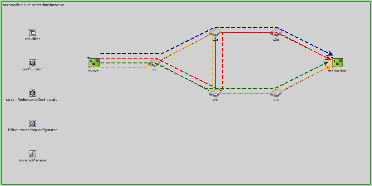
Redundant Path Visualization
The following figures illustrate how the automatic configurators set up redundant paths in the network.
The first figure shows the computed 4 redundant paths through the network.
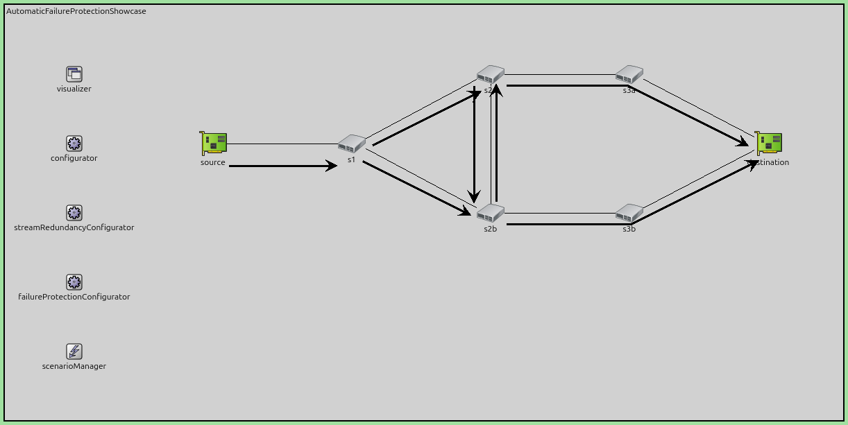
The second figure shows how the redundant paths translated into replication and merge points. Nodes replicate packets where multiple arrows point outwards: s1, s2a, s2b. Nodes eliminate duplicates where multiple arrows point inwards: s2a, s2b, destination.
Note
When a node is doing both, it first eliminates and then replicates packets.
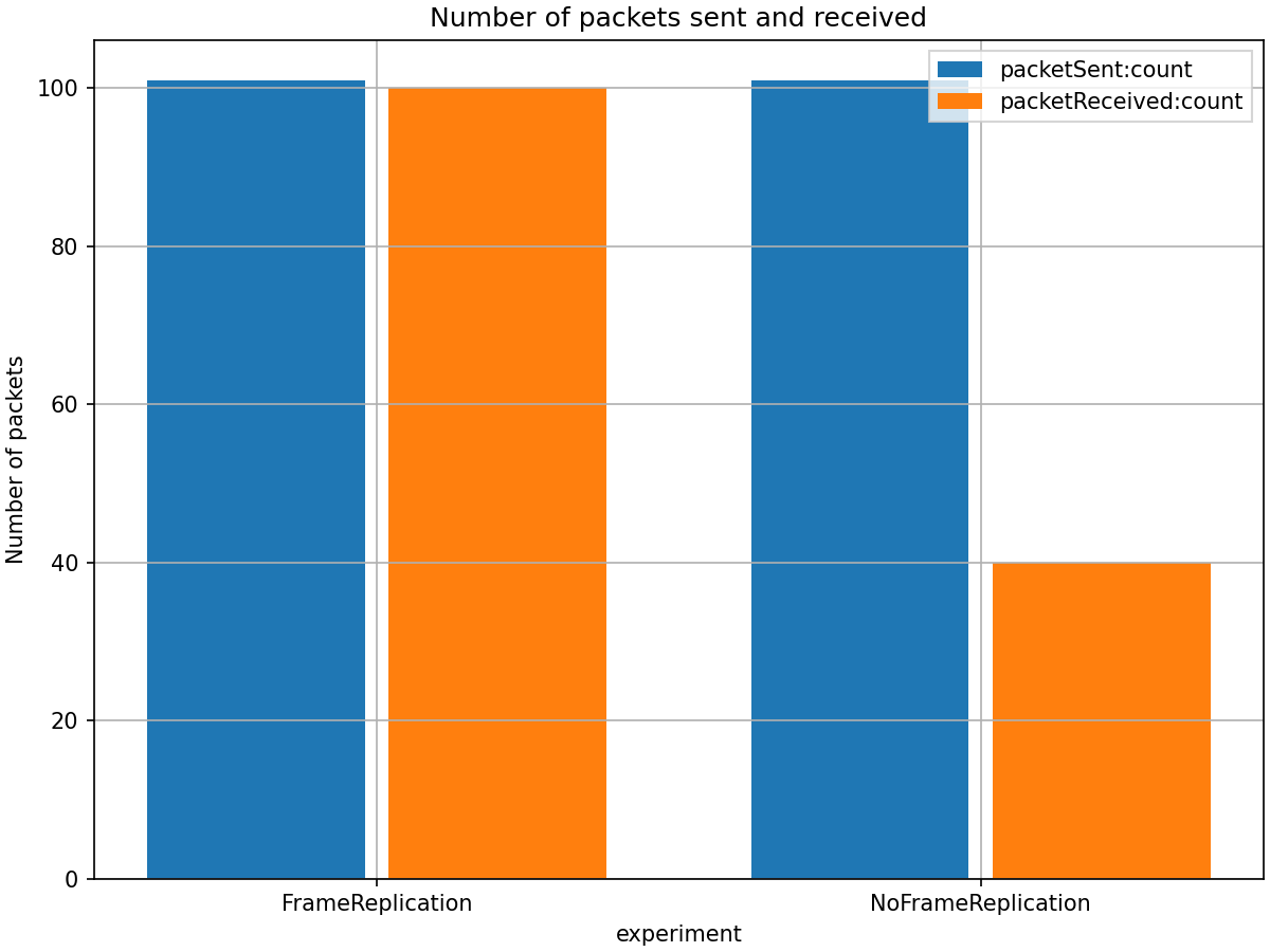
Results
NoFrameReplication Configuration
Without frame replication, the network has a single point of failure. When switch s2a
crashes at 20ms, all packets following that path are lost. After the switch recovers
at 80ms, packet delivery resumes, but packets sent during the outage period (20-80ms)
are permanently lost.
FrameReplication Configuration
With frame replication enabled, the source replicates packets and sends them
along multiple redundant paths. When s2a crashes, packets continue to be
delivered via the alternative path through s2b and s3b. This ensures
continuous packet delivery throughout the simulation even during the failure period.
Here is the number of received and sent packets:
The following figure shows the end-to-end delay for both configurations:
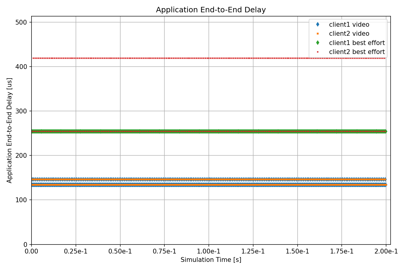
The delay comparison shows:
NoFrameReplication: During the failure period (20-80ms), no packets are delivered, resulting in zero delay measurements. After recovery at 80ms, delay returns to normal levels, but this recovery period represents service interruption.
FrameReplication: Packets continue to be delivered throughout the entire simulation without interruption. Notably, there is no recovery period - the transition during the failure is seamless with no disturbance to packet delivery. The FRER configuration shows slightly higher delay values due to the additional IEEE 802.1 R-Tag header overhead, which increases frame size.
Note
For more details about what the configurator automates, see the Automatic Multipath Stream Configuration showcase.
Sources: omnetpp.ini, AutomaticFailureProtectionShowcase.ned
Try It Yourself
If you already have INET and OMNeT++ installed, start the IDE by typing
omnetpp, import the INET project into the IDE, then navigate to the
inet/showcases/tsn/framereplication/automaticfailureprotection folder in the Project Explorer. There, you can view
and edit the showcase files, run simulations, and analyze results.
Otherwise, there is an easy way to install INET and OMNeT++ using opp_env, and run the simulation interactively.
Ensure that opp_env is installed on your system, then execute:
$ opp_env run inet-4.6 --init -w inet-workspace --install --build-modes=release --chdir \
   -c 'cd inet-4.6.*/showcases/tsn/framereplication/automaticfailureprotection && inet'
This command creates an inet-workspace directory, installs the appropriate
versions of INET and OMNeT++ within it, and launches the inet command in the
showcase directory for interactive simulation.
Alternatively, for a more hands-on experience, you can first set up the workspace and then open an interactive shell:
$ opp_env install --init -w inet-workspace --build-modes=release inet-4.6
$ cd inet-workspace
$ opp_env shell
Inside the shell, start the IDE by typing omnetpp, import the INET project,
then start exploring.
Discussion
Use this page in the GitHub issue tracker for commenting on this showcase.