IEEE 802.11 Fragmentation
Goals
The process of fragmentation is used to improve the performance of 802.11 networks in situations where there is interference, noise, or long distances between nodes. It does this by dividing larger frames into smaller fragments, which increases the probability of successful data transfer. This showcase presents an example of how MAC-level fragmentation is used in INET.
4.6About 802.11 Fragmentation
Fragmentation in 802.11 reduces packet errors in certain situations, e.g. in a noisy environment. A larger frame has a higher chance of getting corrupted than a smaller one. The error correcting mechanism can correct some erroneous bits in a received frame, but as the bit error rate increases, it becomes less likely that it can correct all bit errors. In 802.11, a frame can be fragmented to a maximum of 16 fragments.
The downside is that fragmentation increases overhead, and thus decreases throughput and channel utilization. The smaller packets resulting from fragmentation each have PHY and MAC headers, and each packet transmission might be followed by a contention period and ACK (depending on block ack policy and whether TXOP is used). Also, fragmentation increases delay, because an incoming packet only arrives at the application when all of its fragments have been received.
802.11 Fragmentation in INET
In INET, 802.11 fragmentation is controlled by fragmentation policies
in Ieee80211Mac. By default, the Dcf and Hcf submodules
of Ieee80211Mac contain a fragmentation policy submodule
(at mac.dcf.originatorMacDataService.fragmentationPolicy
and mac.hcf.originatorMacDataService.fragmentationPolicy).
The default fragmentation policy type is BasicFragmentationPolicy.
BasicFragmentationPolicy has just one parameter,
fragmentationThreshold. Frames larger than this value are fragmented.
The value includes the MAC header, the payload, and the MAC trailer.
The MAC overhead (header + trailer) is 28 bytes with DCF and 30 bytes with HCF.
The default for this parameter is 1500 bytes.
Note
Caveat: In addition to fragmentationThreshold, Ieee80211Mac also
has a parameter named mtu (maximum transfer unit), which appears to be
similar in purpose. However, MTU controls IP level fragmentation
on the interface the MAC is part of, i.e. it is actually used by the IP module
instead of the MAC. The two are related; for example, by setting MTU to an
appropriately small value, one can achieve that 802.11 fragmentation is
never triggered (for IP packets at least).
The Model
The example simulation contains two wireless nodes. One of them sends large UDP packets to the other via Wifi in a noisy environment. The simulation will be run with fragmentation turned off and turned on. We’ll examine the effect of fragmentation on the Wifi performance. We’ll also see how TXOP and block acknowledgments affect the performance. Furthermore, we’ll examine the domain of effectiveness for fragmentation.
The example simulation uses the following network:
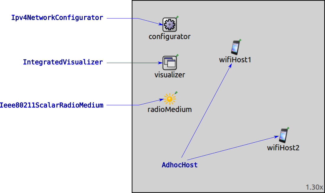
The network contains two AdhocHost’s named wifiHost1 and wifiHost2.
It also contains an Ipv4NetworkConfigurator, an IntegratedCanvasVisualizer,
and an Ieee80211RadioMedium module.
Configuration keys for the UDP traffic, the radio, and the radio medium are defined
in the General configuration in omnetpp.ini.
wifiHost1 sends 2000-byte UDP packets to wifiHost2 every 0.5 seconds,
which corresponds to about 32 Mbps of application-level traffic. The hosts operate
in 802.11g mode with 54 Mbps data rate. Here is the traffic configuration in
omnetpp.ini:
*.wifiHost1.numApps = 1
*.wifiHost1.app[0].typename = "UdpBasicApp"
*.wifiHost1.app[0].destAddresses = "wifiHost2"
*.wifiHost1.app[0].destPort = 4000
*.wifiHost1.app[0].sendInterval = 0.5ms
*.wifiHost1.app[0].messageLength = 2000Byte

*.wifiHost2.numApps = 1
*.wifiHost2.app[0].typename = "UdpSink"
*.wifiHost2.app[0].localPort = 4000
We make the environment noisy by lowering the transmission power. Also, to make the
simulation more precise, we lower various thresholds to prevent certain shortcuts
in the computations from kicking in. Here is the configuration in
omnetpp.ini:
*.wifiHost*.wlan[*].radio.receiver.energyDetection = -105dBm
*.wifiHost*.wlan[*].radio.receiver.sensitivity = -105dBm
*.wifiHost*.wlan[*].radio.receiver.snirThreshold = 0dB

*.wifiHost*.wlan[*].radio.transmitter.power = 0.08mW
We want to demonstrate that fragmenting packets is advantageous in a noisy environment, so we set the transmission power accordingly. If there is too much noise, the fragmentation doesn’t make any difference, as communication becomes impossible. If there is too little noise, fragmentation is disadvantageous due to the extra overhead.
The simulation will be run with four scenarios. Each scenario aims to improve the noisy channel performance of the previous one. They are defined in the following configurations:
DCFnofrag: The MAC uses DCF, and there is no fragmentation. It is expected that only a few of the large packets will be received successfully; throughput will be low.DCFfrag: The MAC uses DCF, and packets are fragmented. Due to the smaller fragments, packet error rate should decrease, and throughput should increase compared to the previous scenario.HCFfrag: The MAC uses HCF, packets are fragmented, and transmitted during a TXOP. Throughput should increase even more, as the sender node doesn’t have to contend for channel access before transmitting each packet (although packets are ACKed individually).HCFfragblockack: This is the same as the previous scenario, but block acknowledgments are enabled. Throughput should increase yet again, as the receiver node doesn’t have to ACK each packet individually.
The simulations will be run for 10 seconds, and we’ll examine the number of packets
received by the UDP application of wifiHost2, and the application level throughput
(the many small packets resulting from fragmentation doesn’t affect the number of packets
received by the UDP application, because they are defragmented by the MAC before they arrive
at the UDP app).
Let’s look at the details of the four configurations. Here is DCFnofrag from
omnetpp.ini:
[Config DCFnofrag]

**.mac.dcf.originatorMacDataService.fragmentationPolicy.fragmentationThreshold = 2250B
It just sets a fragmentation threshold higher than the packet size to avoid fragmentation.
In the next configuration, DCFfrag, we turn on fragmentation. Here is the
configuration in omnetpp.ini:
[Config DCFfrag]

**.mac.dcf.originatorMacDataService.fragmentationPolicy.fragmentationThreshold = 250B
It sets a fragmentation threshold value smaller than the packet size. Packets will be fragmented to 250-byte pieces. Each packet is followed by an ACK and a contention period.
Next, we examine how performance is affected if the small packets are sent
during a TXOP, so the originator MAC doesn’t have to contend for the channel
after transmitting each packet. In the next configuration, HCFfrag,
the MAC will use HCF instead of DCF, and take advantage of video priority TXOP.
Here is the configuration in omnetpp.ini:
[Config HCFfrag]

*.wifiHost*.wlan[*].mac.qosStation = true
*.wifiHost*.wlan[*].classifier.typename = "QosClassifier"
**.mac.hcf.originatorMacDataService.msduAggregationPolicy.typename = ""
**.mac.hcf.originatorMacDataService.fragmentationPolicy.fragmentationThreshold = 250B
It sets the same fragmentation threshold as the previous configuration. QoS is enabled (so the MAC uses HCF). A classifier is added to sort packets into the video priority category. Frame aggregation is turned off, because we don’t want to aggregate our fragments into a larger frame.
Packets are transmitted without contention during the TXOP, but all of them are ACKed individually.
In the final configuration, HCFfragblockack, we extend the previous configuration
and turn on block acks, so a group of packets can be ACKed.
When block acks are enabled, the sender node sends a block ack request after transmitting a certain number of frames (by default, five). The receiver node then sends a block ack, which contains information about which packets were received correctly, and which weren’t. The incorrectly received ones can be retransmitted by the sender.
Here is the configuration:
[Config HCFfragblockack]
extends = HCFfrag

*.wifiHost*.wlan[*].mac.hcf.isBlockAckSupported = true
This configuration just enables block acks. The default block ack threshold is used, i.e. block ack requests are sent after five frames.
Results
Here are the results from the simulations:
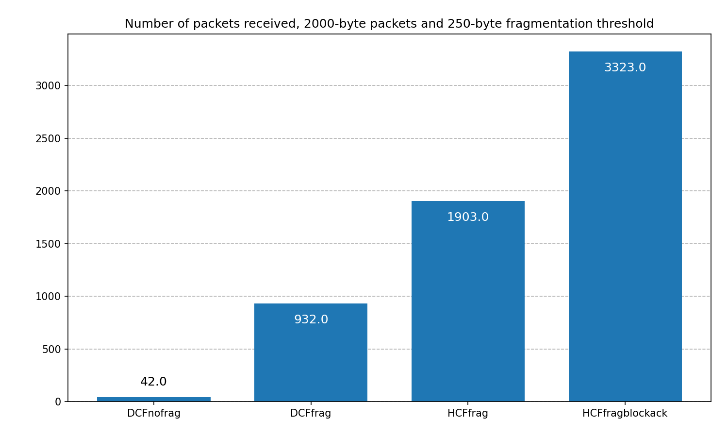
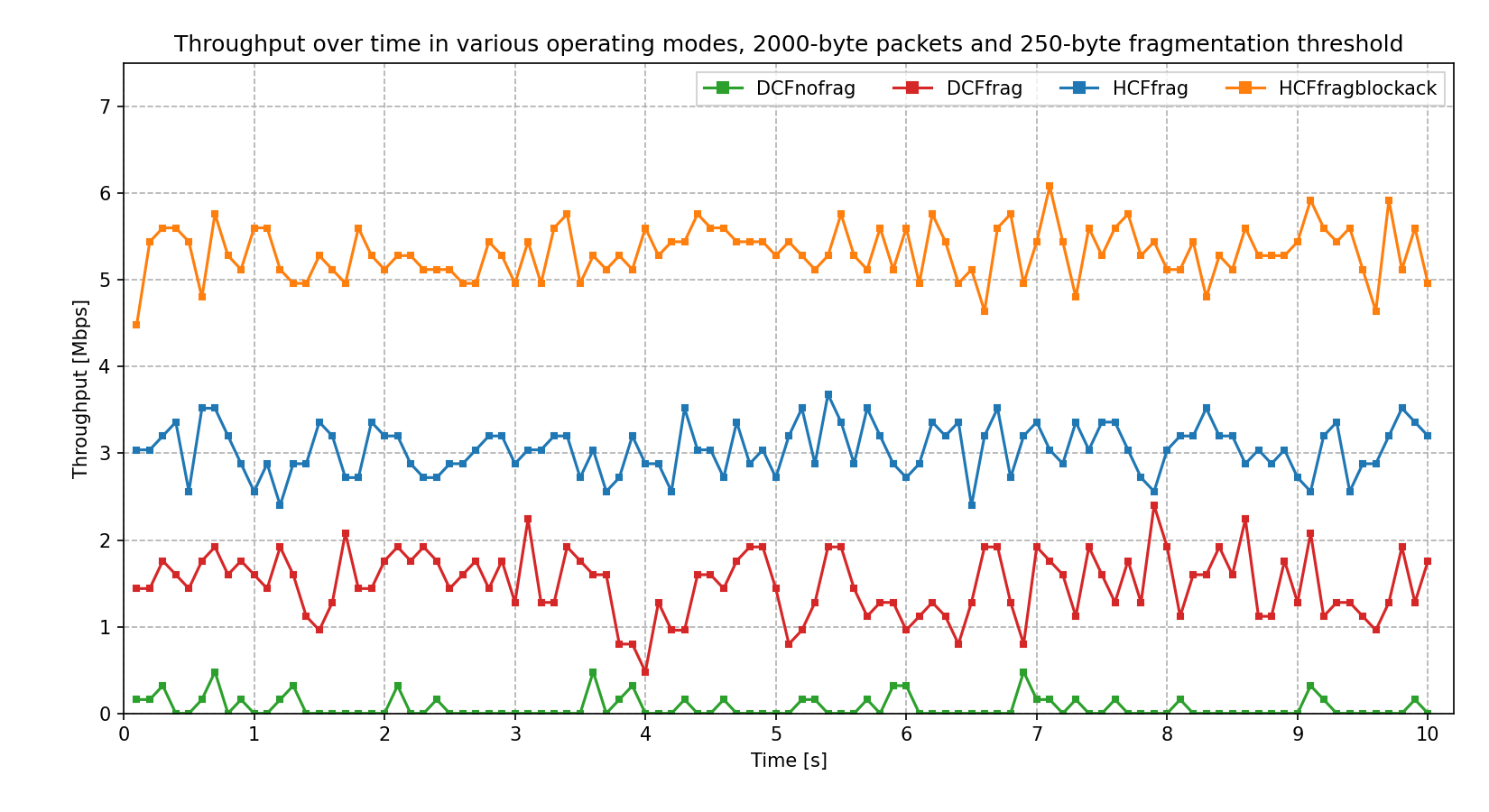
In our setup, the throughput is the lowest when packets are not fragmented
(DFCnofrag line), because very few packets are received correctly.
Throughput improves considerably (by a factor of 20) when fragmentation
is turned on (DCFfrag line). The use of TXOPs (HCFfrag line) again brings
a two-fold increase in througput by eliminating contention periods.
The use of block ACKs (HCFfragblockack line) brings another two-fold improvement.
Further Analysis
We ran some parameter studies to examine the domain of effectiveness for fragmentation. We based the parameter studies on the above simulations. We examined the average application-level throughput. (The noise level, transmission power, and other settings are the same as in the above configurations unless otherwise noted.)
First, the iteration variable was the packet size (going from 100B to 2500B), with a constant fragmentation threshold of 250 bytes:
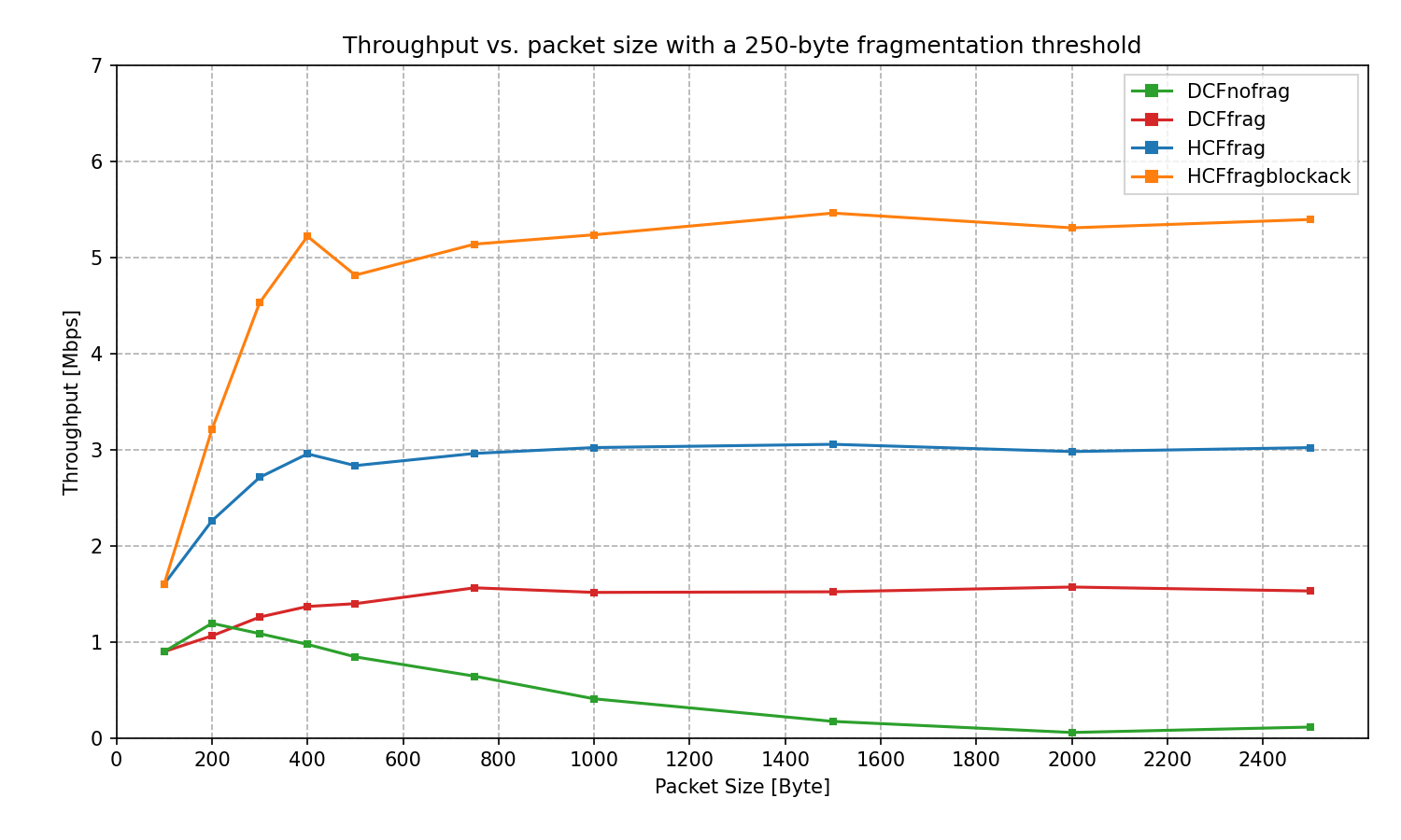
Performance decreases with packet size in the DCFnofrag case, as larger packets
have more chance for becoming corrupted. In the cases where fragmentation is enabled,
the throughput follows a similar curve (increasing at the beginning, and fairly
constant after that). At small packet sizes, the 802.11 overhead is significant.
As the packet size increases above 1000B, throughput doesn’t change substantially.
The difference in magnitude between the three curves of DCFfrag, HCFfrag,
and HCFfragblockack is due to the improvements of each configuration: the use
of TXOP increases throughput, and the use of TXOP + block acks increases it further.
Secondly, the fragmentation threshold was iterated, using a 1000-byte packet size:
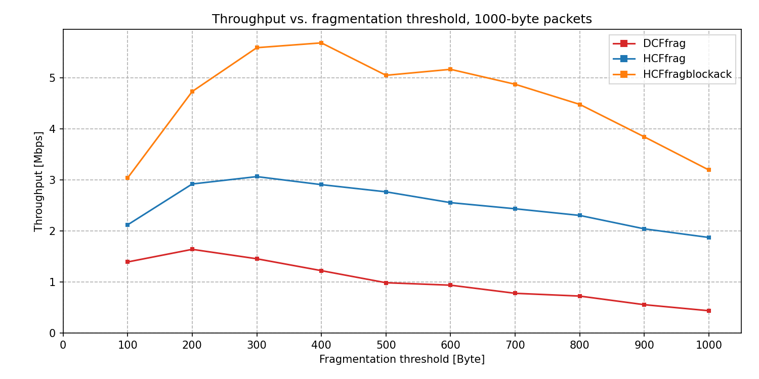
The three curves are similar in shape to each other in this case. The difference in magnitude between them can be attributed to the use of TXOP and TXOP + block ack.
Next, the packet size was iterated, but on a wider range (from 100B to 6000B). The MAC can fragment packets to a maximum of 16 fragments. Due to the larger packets, the fragmentation threshold was set to around 1/16th of the packet size (taking MAC headers into account), so that the MAC always fragments packets to 16 pieces.
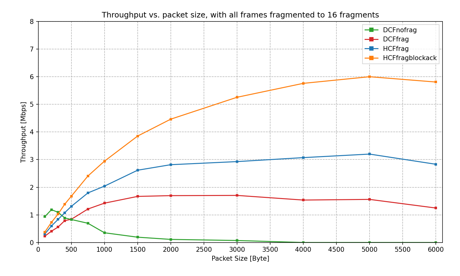
DCFnofrag has an advantage when packets are small since fragmenting small packets
to 16 fragments entails a lot of overhead. Otherwise, the three curves where fragmentation
is enabled are similar, and the difference in magnitude is attributed to the use of TXOP
and TXOP + block ack.
Then, the transmission power was iterated to examine performance at different noise levels.
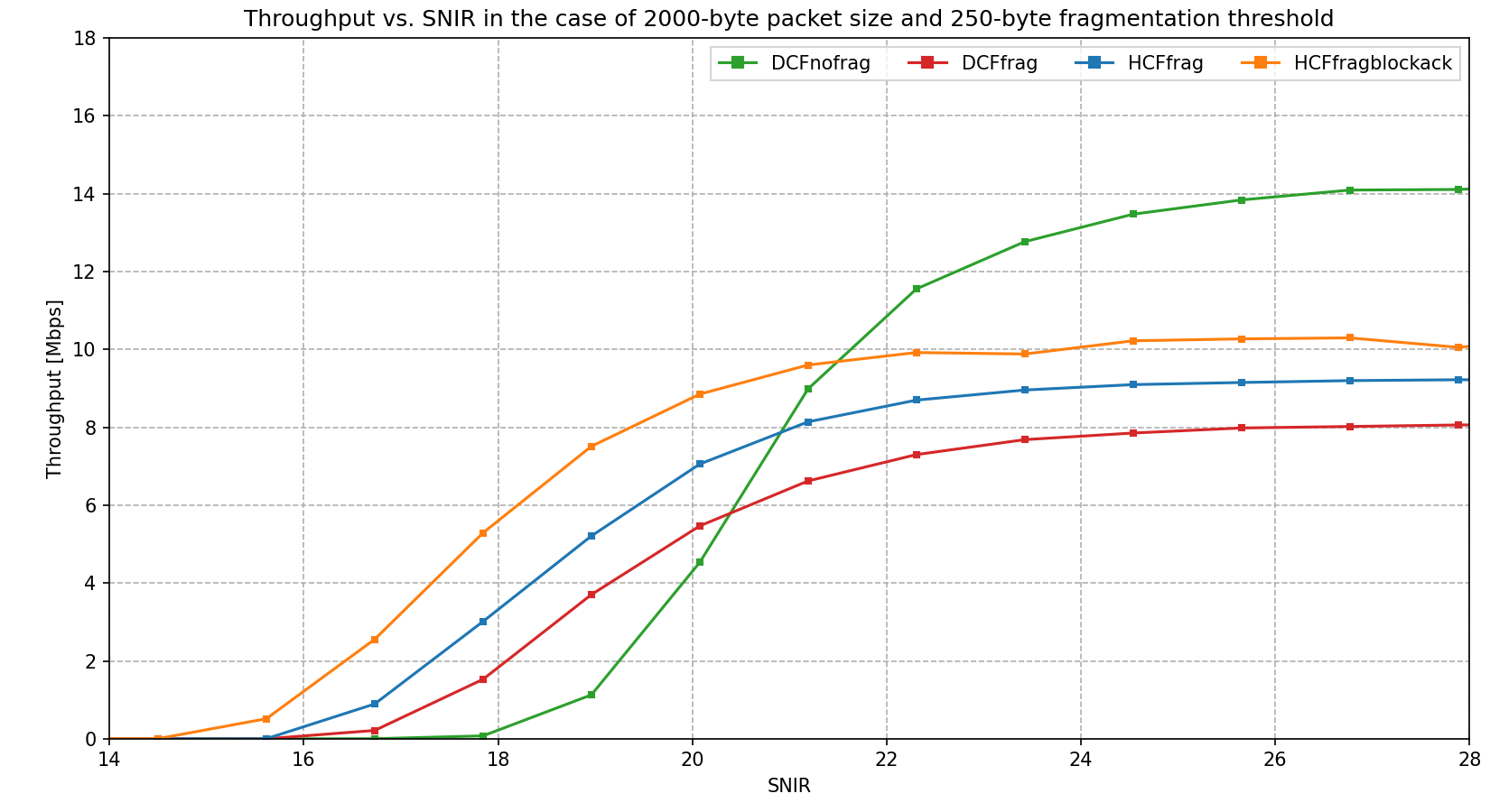
It is apparent that in this scenario, the domain in which fragmentation is useful is a very small range. Above a certain SNIR threshold, the fragmentation decreases performance, and below another threshold, it doesn’t make any difference because all packets are lost.
Note
The parameter study configurations are defined in parameterstudy.ini. The charts are available in ParameterStudy.anf.
Sources: omnetpp.ini, FragmentationShowcase.ned
Try It Yourself
If you already have INET and OMNeT++ installed, start the IDE by typing
omnetpp, import the INET project into the IDE, then navigate to the
inet/showcases/wireless/fragmentation folder in the Project Explorer. There, you can view
and edit the showcase files, run simulations, and analyze results.
Otherwise, there is an easy way to install INET and OMNeT++ using opp_env, and run the simulation interactively.
Ensure that opp_env is installed on your system, then execute:
$ opp_env run inet-4.6 --init -w inet-workspace --install --build-modes=release --chdir \
   -c 'cd inet-4.6.*/showcases/wireless/fragmentation && inet'
This command creates an inet-workspace directory, installs the appropriate
versions of INET and OMNeT++ within it, and launches the inet command in the
showcase directory for interactive simulation.
Alternatively, for a more hands-on experience, you can first set up the workspace and then open an interactive shell:
$ opp_env install --init -w inet-workspace --build-modes=release inet-4.6
$ cd inet-workspace
$ opp_env shell
Inside the shell, start the IDE by typing omnetpp, import the INET project,
then start exploring.
Discussion
Use this page in the GitHub issue tracker for commenting on this showcase.