Eager Gate Schedule Configuration
Goals
This showcase demonstrates how the eager gate schedule configurator can set up schedules in a simple network.
4.4The Model
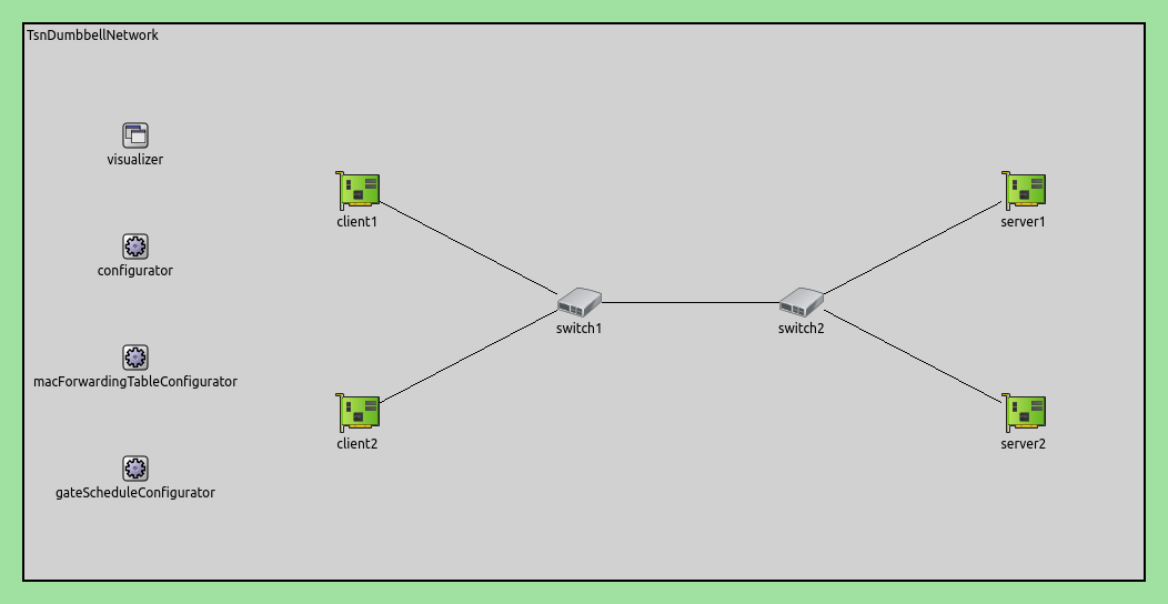
The simulation uses the following network:

Here is the configuration:
[Eager]
network = inet.networks.tsn.TsnDumbbellNetwork
description = "Eager gate scheduling"
sim-time-limit = 0.2s
#record-eventlog = true

*.switch1.typename = "TsnSwitch1"
*.switch2.typename = "TsnSwitch2"

# client applications
*.client*.numApps = 2
*.client*.app[*].typename = "UdpSourceApp"
*.client*.app[0].display-name = "best effort"
*.client*.app[1].display-name = "video"
*.client*.app[0].io.destAddress = "server1"
*.client*.app[1].io.destAddress = "server2"
*.client1.app[0].io.destPort = 1000
*.client1.app[1].io.destPort = 1002
*.client2.app[0].io.destPort = 1001
*.client2.app[1].io.destPort = 1003
*.client*.app[*].source.packetNameFormat = "%M-%m-%c"
*.client*.app[0].source.packetLength = 1000B
*.client*.app[1].source.packetLength = 500B
*.client*.app[0].source.productionInterval = 500us # ~16Mbps
*.client*.app[1].source.productionInterval = 250us # ~16Mbps

# server applications
*.server*.numApps = 4
*.server*.app[*].typename = "UdpSinkApp"
*.server*.app[0..1].display-name = "best effort"
*.server*.app[2..3].display-name = "video"
*.server*.app[0].io.localPort = 1000
*.server*.app[1].io.localPort = 1001
*.server*.app[2].io.localPort = 1002
*.server*.app[3].io.localPort = 1003

# enable outgoing streams
*.client*.hasOutgoingStreams = true

# client stream identification
*.client*.bridging.streamIdentifier.identifier.mapping = [{stream: "best effort", packetFilter: expr(udp.destPort == 1000)},
                                                          {stream: "video", packetFilter: expr(udp.destPort == 1002)},
														  {stream: "best effort", packetFilter: expr(udp.destPort == 1001)},
														  {stream: "video", packetFilter: expr(udp.destPort == 1003)}]

# client stream encoding
*.client*.bridging.streamCoder.encoder.mapping = [{stream: "best effort", pcp: 0},
                                                  {stream: "video", pcp: 4}]

# enable streams
*.switch*.hasIncomingStreams = true
*.switch*.hasOutgoingStreams = true

*.switch*.bridging.streamCoder.decoder.mapping = [{pcp: 0, stream: "best effort"},
                                                  {pcp: 4, stream: "video"}]

*.switch*.bridging.streamCoder.encoder.mapping = [{stream: "best effort", pcp: 0},
                                                  {stream: "video", pcp: 4}]

# enable incoming streams
*.server*.hasIncomingStreams = true

# enable egress traffic shaping
*.switch*.hasEgressTrafficShaping = true

# time-aware traffic shaping with 2 queues
*.switch*.eth[*].macLayer.queue.numTrafficClasses = 2
*.switch*.eth[*].macLayer.queue.queue[0].display-name = "best effort"
*.switch*.eth[*].macLayer.queue.queue[1].display-name = "video"

# automatic gate scheduling
*.gateScheduleConfigurator.typename = "EagerGateScheduleConfigurator"
*.gateScheduleConfigurator.gateCycleDuration = 1ms
# 58B = 8B (UDP) + 20B (IP) + 4B (802.1 Q-TAG) + 14B (ETH MAC) + 4B (ETH FCS) + 8B (ETH PHY)
*.gateScheduleConfigurator.configuration =
   [{pcp: 0, gateIndex: 0, application: "app[0]", source: "client1", destination: "server1", packetLength: 1000B + 58B, packetInterval: 500us, maxLatency: 500us},
    {pcp: 4, gateIndex: 1, application: "app[1]", source: "client1", destination: "server2", packetLength: 500B + 58B, packetInterval: 250us, maxLatency: 500us},
    {pcp: 0, gateIndex: 0, application: "app[0]", source: "client2", destination: "server1", packetLength: 1000B + 58B, packetInterval: 500us, maxLatency: 500us},
    {pcp: 4, gateIndex: 1, application: "app[1]", source: "client2", destination: "server2", packetLength: 500B + 58B, packetInterval: 250us, maxLatency: 500us}]

# gate scheduling visualization
*.visualizer.gateScheduleVisualizer.displayGateSchedules = true
*.visualizer.gateScheduleVisualizer.displayDuration = 100us
*.visualizer.gateScheduleVisualizer.gateFilter = "*.switch1.eth[2].** or *.switch2.eth[0].**.transmissionGate[0] or *.switch2.eth[1].**.transmissionGate[1]"
*.visualizer.gateScheduleVisualizer.height = 16
Results
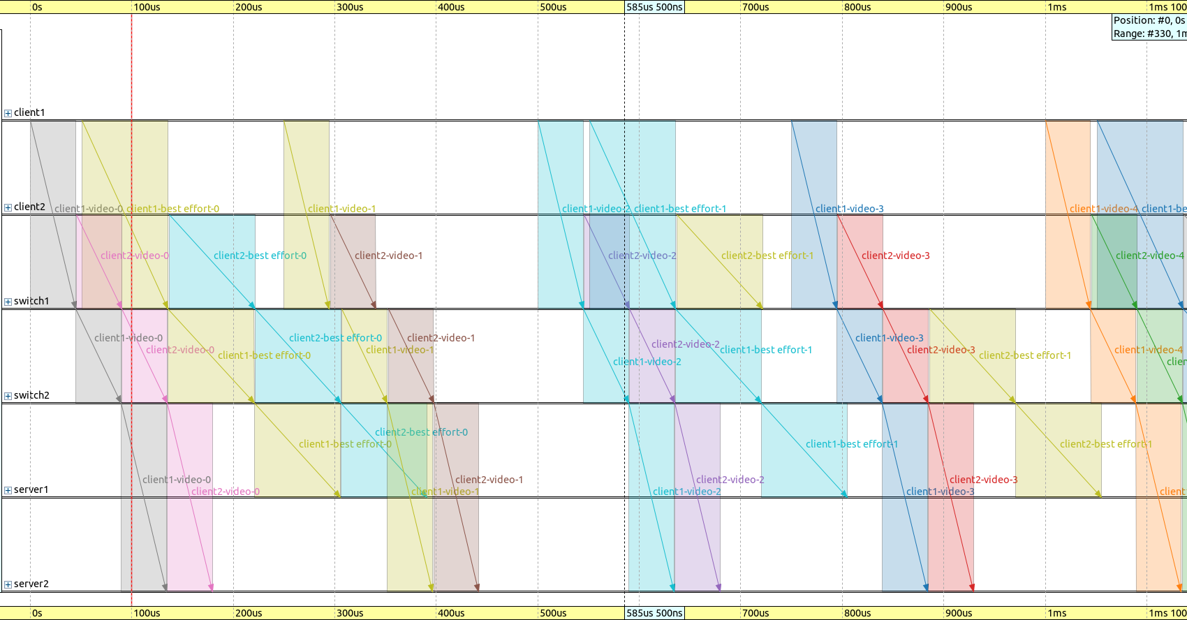
A gate cycle duration of 1ms is displayed on the following sequence chart. Note how time efficient the flow of packets from the sources to the sinks are:

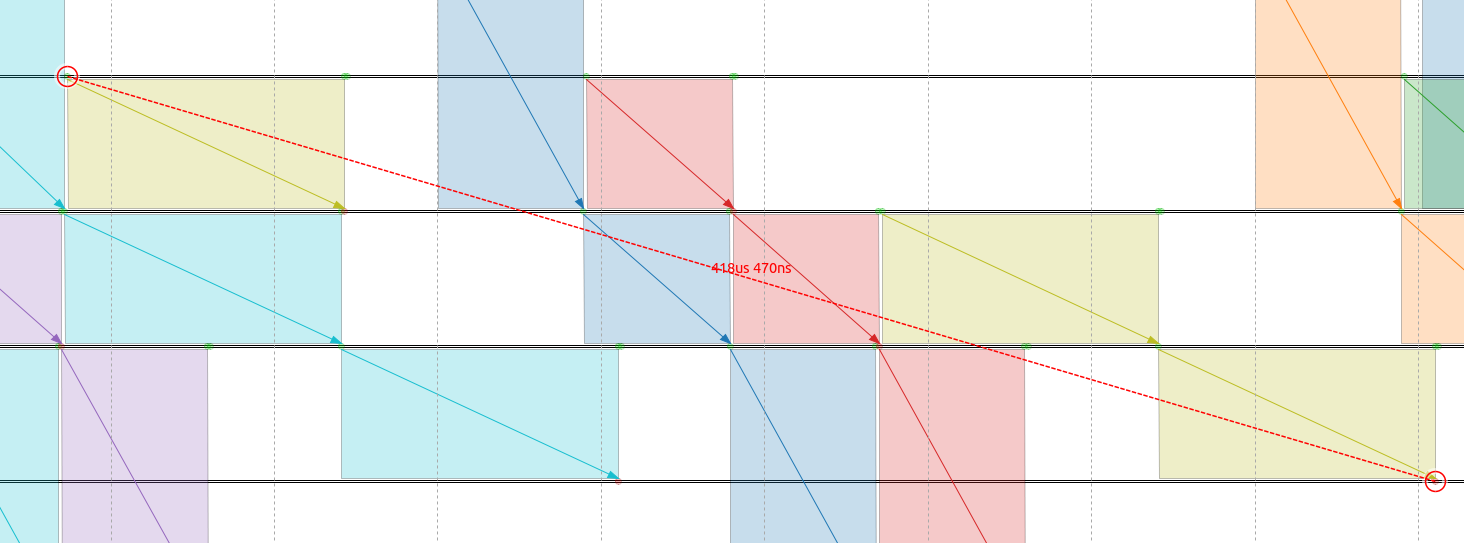
Here is the delay for the second packet of client2 in the best effort traffic class, from the packet source to the packet sink. Note that this stream is the outlier on the above chart. The delay is within the 500us requirement, but it’s quite close to it:

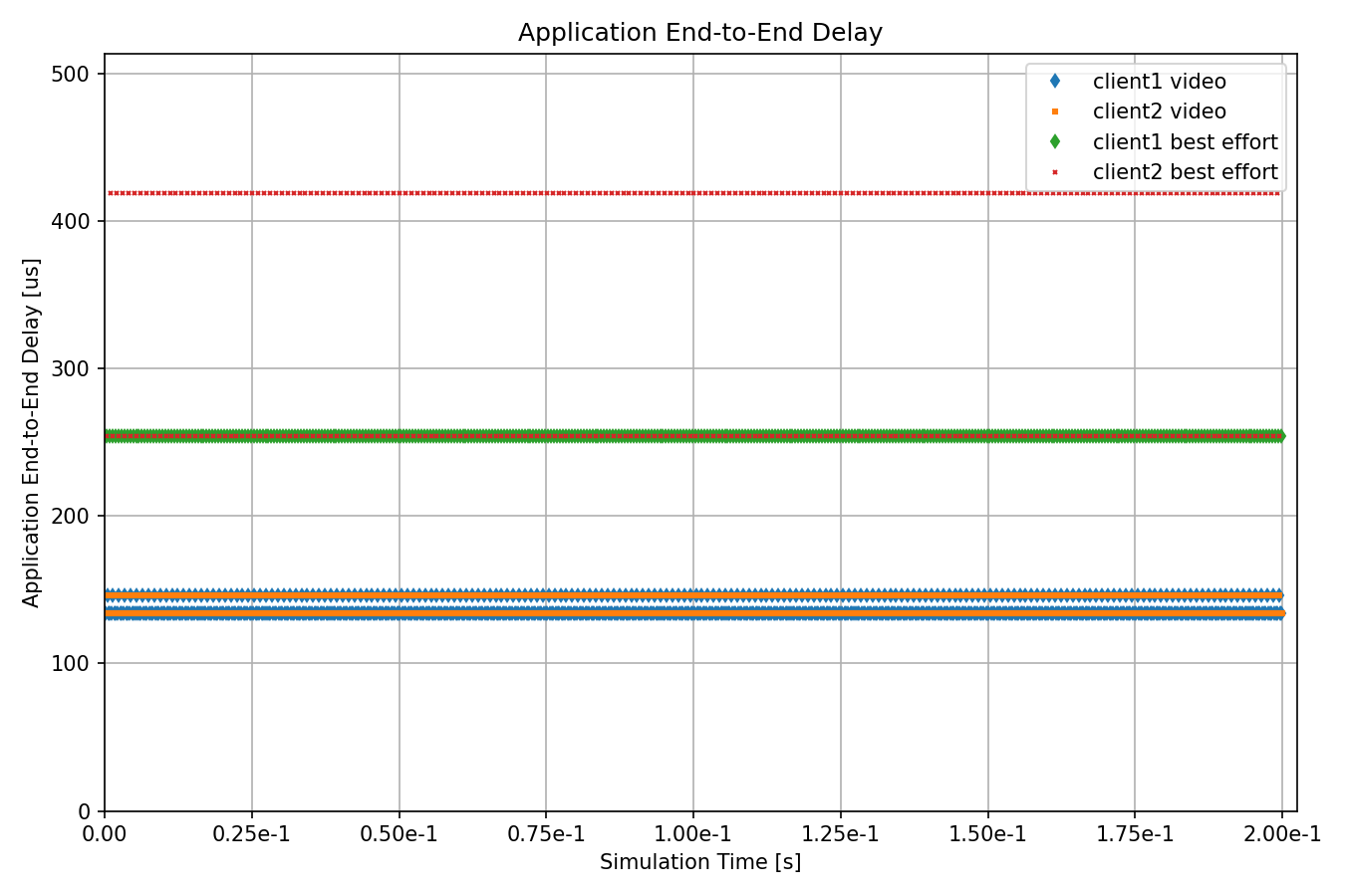
The following chart displays the delay for individual packets of the different traffic categories:

All delay is within the specified constraints.
Note
Both video streams and the client2 best effort stream have two cluster points. This is due to these traffic classes having multiple packets per gate cycle. As the different flows interact, some packets have increased delay.
Sources: omnetpp.ini
Try It Yourself
If you already have INET and OMNeT++ installed, start the IDE by typing
omnetpp, import the INET project into the IDE, then navigate to the
inet/showcases/tsn/gatescheduling/eager folder in the Project Explorer. There, you can view
and edit the showcase files, run simulations, and analyze results.
Otherwise, there is an easy way to install INET and OMNeT++ using opp_env, and run the simulation interactively.
Ensure that opp_env is installed on your system, then execute:
$ opp_env run inet-4.4 --init -w inet-workspace --install --chdir \
   -c 'cd inet-4.4.*/showcases/tsn/gatescheduling/eager && inet'
This command creates an inet-workspace directory, installs the appropriate
versions of INET and OMNeT++ within it, and launches the inet command in the
showcase directory for interactive simulation.
Alternatively, for a more hands-on experience, you can first set up the workspace and then open an interactive shell:
$ opp_env install --init -w inet-workspace inet-4.4
$ cd inet-workspace
$ opp_env shell
Inside the shell, start the IDE by typing omnetpp, import the INET project,
then start exploring.