Crosstalk Between Adjacent IEEE 802.11 Channels
Goals
Crosstalk between adjacent IEEE 802.11 channels refers to the interference that can occur when transmissions on different channels overlap in frequency. In the IEEE 802.11 standard, which is commonly used for wireless networking, there are a number of different channels that can be used, depending on the frequency range (e.g. 2.4 GHz or 5 GHz). In a real-world scenario, it is rare for all devices to be using the same channel, and there may be multiple networks operating on different channels at the same location. When transmissions on adjacent channels overlap in frequency, they can interfere with each other and affect the performance of the network.
INET has support for simulating communication on different IEEE 802.11 channels, both in the 2.4 GHz and 5 GHz frequency ranges. In this showcase, we will demonstrate how to use overlapping and non-overlapping channels in simulations and how transmissions on different channels can interfere with each other. By the end of this showcase, you will understand the impact of crosstalk between adjacent 802.11 channels and how it can be simulated.
This showcase divides the topic of the simulation of different Wifi channels into three cases:
Completely overlapping frequency bands: all nodes communicate on the same Wifi channel
Independent frequency bands: nodes communicate on different channels that don’t affect each other
Partially overlapping frequency bands: nodes communicate on adjacent channels, which interfere with each other
Each case is demonstrated with an example simulation.
4.6The model
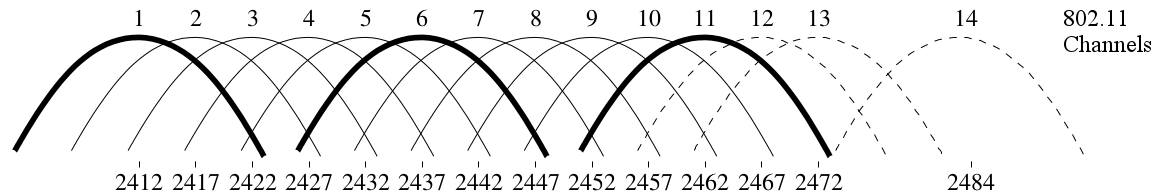
The 2.4 GHz frequency range in 802.11g, for example, can use a limited number of channels (13 in the EU). The bandwidth of transmissions in 802.11g is 20MHz, and channels are spaced 5MHz apart. Thus adjacent channels overlap, and transmissions on these channels can interfere. There can be a few independent channels, where there is no cross-channel interference, e.g., Channels 1, 6, and 11, as illustrated below.
In INET, the scalar analog model represents signals with a scalar signal power, and a constant center frequency and bandwidth. The scalar model can only handle situations when the spectra of two concurrent signals are identical or don’t overlap at all. When using the dimensional analog model, signal power can change in both time and frequency; more realistic signal shapes can be specified. This model is also able to calculate the interference of signals whose spectra partially overlap.
There are example simulations for the three cases outlined in the Goals section. In the cases of completely overlapping channels and independent channels, the simulations use the scalar analog model; in the case of the partially overlapping channels, the dimensional analog model is used.
All simulations use variations of the same network, which is illustrated by the image below:
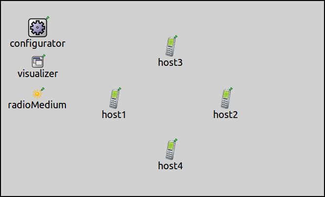
The networks contain four AdhocHost’s, named host1 to
host4. The networks also contain an Ipv4NetworkConfigurator
module, an IntegratedCanvasVisualizer module, and one or two Ieee80211RadioMedium modules.
The number of the radio medium modules varies in the networks
for the different simulations. All hosts
are within communication range of each other.
The hosts are arranged in
a rectangle; host1 is configured to send UDP packets to host2, and similarly,
host3 sends UDP packets to host4. The configuration keys common to all
simulations, specifying e.g. traffic generation and visualization, are
defined in the General configuration in omnetpp.ini.
The following sections detail the three configurations.
Note
By default, 802.11 hosts and access points in INET are configured to use the same Wifi channel (Channel 1).
Completely Overlapping Frequency Bands
The simulation for this case demonstrates the hosts communicating on the
same Wifi channel, the default Channel 1. The simulation can be run by
selecting the CompletelyOverlappingFrequencyBands configuration from
the ini file. The configuration doesn’t specify anything beyond the keys
of the General configuration, so it’s empty:
[Config CompletelyOverlappingFrequencyBands]
sim-time-limit = 1s
network = CrosstalkShowcaseOneRadioMediumModule
Since the frequency and bandwidth of transmissions for all hosts are exactly the same, inferring which transmissions interfere is obvious (all of them). In this case, all hosts need to use the same radio medium module, and the scalar analog model is sufficient. The following video shows the node-pairs communicating; the number of sent/received packets is displayed above the nodes, as well as the state of the contention modules of the transmitting hosts.
At first, the two source nodes, host1 and host3, start
transmitting at the same time. The transmissions collide, and neither
destination host is able to receive any of them correctly. The collision
avoidance mechanism takes effect, and host3 wins channel access.
Both nodes can transmit their data successfully after one another.
Independent Frequency Bands
In this case, we are modeling host-pairs that are communicating on different, non-overlapping Wifi channels (e.g., Channels 1 and 6). Since the channels are independent, it is obvious that there won’t be any interference. The scalar analog model is sufficient for this case.
In the first configuration for this case, the hosts use the same radio
medium module. The simulation can be run by choosing the
IndependentFrequencyBandsOneRadioMediumModule configuration
from the ini file. The radios of the two host pairs are configured
to use the non-overlapping Channels 1 and 6:
[Config IndependentFrequencyBandsOneRadioMediumModule]
sim-time-limit = 1s
network = CrosstalkShowcaseOneRadioMediumModule

*.host{1..2}.wlan[*].radio.channelNumber = 0
*.host{3..4}.wlan[*].radio.channelNumber = 5
Note
The channel numbers are set to 0 and 5 because in INET’s 802.11 model, the channels are numbered from 0, so that this setting corresponds to Wifi Channels 1 and 6.
The video below shows the hosts communicating:
Since host-pairs communicate on independent channels, there is no
interference. host1 and host3 can transmit simultaneously, and
their transmissions are correctly receivable by both destination hosts.
Note that all transmissions are sent to all hosts by the radio medium
module.
Since they transmit/receive on different, non-interfering channels, it is obvious that host4 cannot receive host1’s
transmissions, just as host2 cannot receive host3’s
transmissions. Yet the radio medium module sent all transmissions to all
hosts, where the radio module decided that some of the transmissions
cannot be received because the host’s receiver is set to a different
channel.
The simulation can be optimized by omitting these unnecessary message sends by the radio medium, by using two radio medium modules and configuring the non-interfering host-pairs to use different radio mediums. By using two radio medium modules, the simulation scales better as the number of nodes increases.
The second example simulation demonstrates the use of two radio medium
modules to optimize the simulation. The simulation can be run by
choosing the IndependentFrequencyBandsTwoRadioMediumModules
configuration from the ini file:
[Config IndependentFrequencyBandsTwoRadioMediumModules]
sim-time-limit = 1s
network = CrosstalkShowcaseTwoRadioMediumModules

*.host{1..2}.wlan[*].radio.radioMediumModule = "radioMedium1"
*.host{3..4}.wlan[*].radio.radioMediumModule = "radioMedium2"

# Wifi channel settings - not required
*.host{1..2}.wlan[*].radio.channelNumber = 0
*.host{3..4}.wlan[*].radio.channelNumber = 5
Here, the radios of each host pair are set to use one of the two radio medium modules
(by default, radios use the one named radioMedium).
Also, the non-overlapping channels are configured,
but from the perspective of interference, it doesn’t make any difference,
as the use of two radio modules prevents interference anyway.
The following video shows the host-pairs communicating:
The host pairs communicate without interference. Notice that there are only message sends between hosts using the same radio medium module.
Partially Overlapping Frequency Bands
In this case, the host pairs communicate on different Wifi channels, which
partially overlap in frequency. The scalar analog model is insufficient to
simulate partially overlapping channels, thus we use the dimensional analog model.
The example simulation for this case uses the
CrosstalkShowcaseOneRadioMediumModule network.
The simulation is specified
in the PartiallyOverlappingFrequencyBands configuration.
The radio medium module and radios in the hosts are configured to use the dimensional analog model.
The host pairs are set to adjacent Wifi Channels 1 and 2.
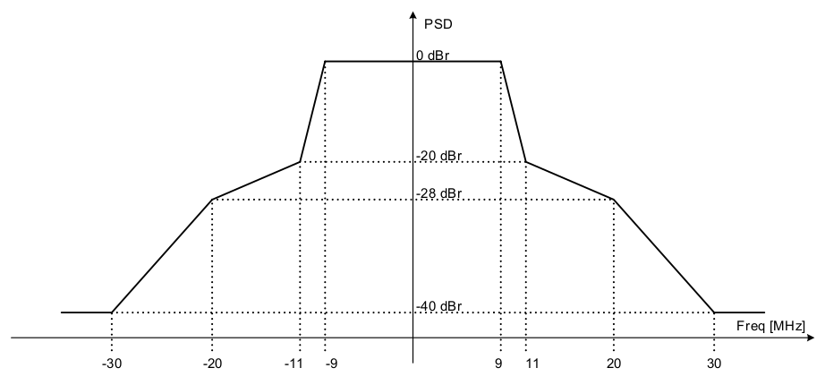
Also, a more realistic signal spectrum is configured, based on the spectral mask
of OFDM transmissions, as in the 802.11 standard:
Here is the configuration in omnetpp.ini:
[Config PartiallyOverlappingFrequencyBands]
sim-time-limit = 1s
network = CrosstalkShowcaseOneRadioMediumModule

*.host*.wlan[*].radio.signalAnalogRepresentation = "dimensional"
*.radioMedium.signalAnalogRepresentation = "dimensional"
*.radioMedium.backgroundNoise.powerSpectralDensity = -110dBmWpMHz
*.radioMedium.backgroundNoise.power = nan

*.host{1..2}.wlan[*].radio.channelNumber = 0
*.host{3..4}.wlan[*].radio.channelNumber = 1

*.host*.wlan[*].radio.transmitter.frequencyGains = "left c-b*1.5 -40dB linear c-b -28dB linear c-b*0.5-1MHz -20dB linear c-b*0.5+1MHz 0dB linear c+b*0.5-1MHz 0dB linear c+b*0.5+1MHz -20dB linear c+b -28dB linear c+b*1.5 -40dB right"
The following video shows the host pairs communicating:
Even though they are on different channels, the transmissions interfere.
In the beginning, host1 and host3 transmit simultaneously,
and neither transmission can be successfully received.
Due to the collision avoidance mechanism, one of the transmitting hosts
defers from transmitting, and the subsequent transmissions are successful.
Sources: omnetpp.ini, Crosstalk.ned
Try It Yourself
If you already have INET and OMNeT++ installed, start the IDE by typing
omnetpp, import the INET project into the IDE, then navigate to the
inet/showcases/wireless/crosstalk folder in the Project Explorer. There, you can view
and edit the showcase files, run simulations, and analyze results.
Otherwise, there is an easy way to install INET and OMNeT++ using opp_env, and run the simulation interactively.
Ensure that opp_env is installed on your system, then execute:
$ opp_env run inet-4.6 --init -w inet-workspace --install --build-modes=release --chdir \
   -c 'cd inet-4.6.*/showcases/wireless/crosstalk && inet'
This command creates an inet-workspace directory, installs the appropriate
versions of INET and OMNeT++ within it, and launches the inet command in the
showcase directory for interactive simulation.
Alternatively, for a more hands-on experience, you can first set up the workspace and then open an interactive shell:
$ opp_env install --init -w inet-workspace --build-modes=release inet-4.6
$ cd inet-workspace
$ opp_env shell
Inside the shell, start the IDE by typing omnetpp, import the INET project,
then start exploring.
Discussion
Use this page in the GitHub issue tracker for commenting on this showcase.