3D Mobility
Goals
Modeling the movement of objects in three dimensions is essential when simulating scenarios involving aircraft, drones, and similar entities. This showcase demonstrates how INET can be used to generate and visualize three-dimensional mobility. This can be useful for understanding and evaluating the behavior of communication systems in such environments.
4.6Overview
In INET, mobility is added to nodes in the form of modules that represent mobility models. A large number of mobility models have been provided with INET, and they can also be combined. This showcase demonstrates producing movement in three dimensions.
One way to generate spatial movement is to use mobility models that support it out of the box, for example, LinearMobility, RandomWaypointMobility, MassMobility, TurtleMobility, or BonnMotionMobility. Spatial movement can also be produced using a superposition of several mobility models (where at least one of them must support movement in the Z axis). We show an example for both approaches.
In these example simulations, we’ll make use of 3D visualization based on OpenSceneGraph (OSG). To try these examples yourself, make sure that your OMNeT++ installation has been compiled with OSG support. If it is not, you won’t be able to switch to the 3D view using the globe icon on the Qtenv toolbar.

The model
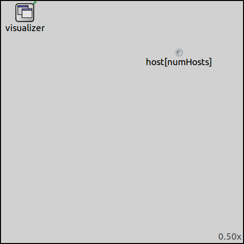
The simulations use the SpatialMobilityShowcase network. It contains a configurable number of mobile nodes (hosts) and an IntegratedVisualizer module.
Here are the key parts of the configuration regarding the visualization of the scene in 3D:
# scene visualization
*.visualizer.osgVisualizer.sceneVisualizer.clearColor = "skyblue"
*.visualizer.osgVisualizer.sceneVisualizer.sceneImage = "showcases/desert"
*.visualizer.osgVisualizer.sceneVisualizer.sceneImageSize = 5000m
*.visualizer.osgVisualizer.sceneVisualizer.axisLength = 1000m
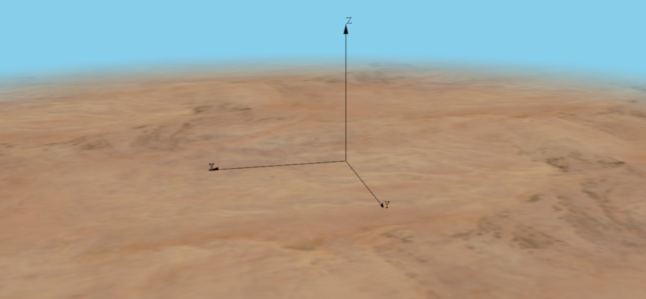
We use the desert image as the ground,
and set the background color (clearColor) to skyblue.
The coordinate axes can be displayed by setting the axisLength parameter.
Additional settings (not shown above) stretch the rendered scene a little larger
than the constraint area of the mobility models to enhance visual appearance.
Further settings enable various effects in the mobility visualization. Note, however, that at the time of writing, not all features are implemented in the MobilityOsgVisualizer (practically, only trail visualization is).
When simulations are run, the scene looks like the following in the 3D view:
Examples and Results
Spiral
The first example simulation is run using only one host. The 3D model of the host
can be set with the osgModel parameter. In this example, we use glider.osgb.
For better visibility, the glider is scaled up to 100 times its original size. It
is also rotated by 180 degrees so that it faces forward as it moves.
*.host[*].osgModel = "3d/glider.osgb.100.scale.0,0,180.rot"
We configure the glider to move along a spiral path. This is achieved using the SuperpositioningMobility mobility model with LinearMobility and CircleMobility as its components. The superposition of a circular motion in the XY plane and a linear motion in the positive Z direction will yield a spiral path. This looks like the following in the configuration:
*.host[0].mobility.typename = "SuperpositioningMobility"
*.host[0].mobility.numElements = 2
*.host[0].mobility.orientationComposition = "faceForward"
*.host[0].mobility.element[0].typename = "LinearMobility"
*.host[0].mobility.element[0].initialX = 0m
*.host[0].mobility.element[0].initialY = 0m
*.host[0].mobility.element[0].initialZ = 0m
*.host[0].mobility.element[0].initialMovementElevation = 90deg
*.host[0].mobility.element[0].speed = 2mps
*.host[0].mobility.element[1].typename = "CircleMobility"
*.host[0].mobility.element[1].cx = 500m
*.host[0].mobility.element[1].cy = 500m
*.host[0].mobility.element[1].r = 400m
*.host[0].mobility.element[1].speed = 20mps
The following video shows the resulting spiral motion:
Drones
In this example, we simulate the movement of 10 drones. The constraintAreaMinZ
is set to 200 meters only because we do not want the drones to reach the ground.
In this example, we use the drone.ive as the 3D OSG model of the hosts:
*.host[*].osgModel = "3d/drone.ive.100.scale.0,0,90.rot"
The MassMobility model is used in the drones in order to achieve a lifelike motion.
*.host[*].mobility.typename = "MassMobility"
*.host[*].mobility.changeInterval = 1s
*.host[*].mobility.initialMovementHeading = uniform(0deg, 360deg)
*.host[*].mobility.initialMovementElevation = uniform(-90deg, 90deg)
*.host[*].mobility.angleDelta = uniform(-10deg,10deg)
*.host[*].mobility.rotationAxisAngle = uniform(-10deg,10deg)
*.host[*].mobility.speed = uniform(10mps,20mps)
*.host[*].mobility.faceForward = false
The speed of drones is updated at every change interval, but more importantly,
they also turn by a random but small angle. The change angle is nearly parallel
to the XY plane, but not quite: there is a random inclination
denoted by the rotationAxisAngle parameter, which will cause the drones
to ramble in three dimensions.
The following video shows the movement of the drones:
Sources: omnetpp.ini, SpatialMobilityShowcase.ned
Try It Yourself
First, install INET and OMNeT++. Then, start the IDE by typing
omnetpp, import the INET project into the IDE, then navigate to the
inet/showcases/mobility/spatial folder in the Project Explorer. There, you can view
and edit the showcase files, run simulations, and analyze results.
Currently, opp_env-based installation is not recommended for the showcases making use of OSG.
Discussion
Use this page in the GitHub issue tracker for commenting on this showcase.