IEEE 802.11 Quality of Service
Goals
IEEE 802.11 Quality of Service (QoS) is a feature designed to improve the performance of delay-sensitive applications, such as voice, streaming multimedia, and online gaming, by allowing packets to belong to different traffic classes with different transmit priorities. Packets with higher priorities are statistically more likely to be transmitted before lower-priority ones, resulting in lower delay and jitter for delay-sensitive applications.
This showcase demonstrates the use of QoS in INET’s 802.11 MAC model.
4.6About 802.11 QoS
When QoS is enabled in 802.11, the MAC uses a technique called enhanced distributed channel access (EDCA) to provide different treatment to various packet classes. EDCA is part of the hybrid coordination function (HCF). In EDCA, packets are classified into four access categories, each category having a different priority. The categories from lowest to highest priority are the following:
Background
Best effort
Video
Voice
Each access category has its own packet queue. Higher priority packets have a higher chance of being sent than lower priority ones because the MAC waits less before sending the higher priority packets, i.e. the contention backoff duration is lower. Also, the higher priority packets have a shorter contention window, and longer transmit opportunity (TXOP) duration.
802.11 QoS in INET
In INET, the 802.11 QoS features can be enabled by setting the qosStation
parameter to true in Ieee80211Mac. When this parameter is set to true,
the MAC uses the Hcf submodule instead of Dcf.
Also, a classifier module is required to sort packets into access categories. The classifier is an optional submodule of Ieee80211Interface. The example simulation uses the QosClassifier module type, which classifies packets according to their source and destination ports. The port-to-access category mapping is defined by the classifier’s parameters. By default, the mapping is the following (port numbers apply to both UDP and TCP):
port 21: background
port 80: best effort
port 4000: video
port 5000: voice
If either a packet’s source or destination port matches one of the above ports, the packet is classified into the corresponding category. (To be pedantic, QosClassifier actually assigns a 0..7 user priority (UP) value to packets, which the MAC will further map to one of the four access category (AC), using a straightforward hardcoded mapping. UP is a purely technical detail that can be completely ignored for the purposes of our study.)
Note
QoS needs to be enabled in all devices that partake in the communication, because otherwise some of them wouldn’t be able to make sense of some of the features that the Hcf might use, such as block acknowledgment requests, aggregate frames, etc.
The Model
The showcase contains an example simulation featuring a wireless network, with two hosts communicating through an access point. One of the hosts sends data to the other via UDP, using four UDP streams, each corresponding to an access category. We’ll run the simulation with QoS disabled, then with QoS enabled. Traffic is configured with realistic bitrates, i.e. high background and best effort, lower video, and even lower voice traffic.
After running the simulations, we analyze the results. We take a look at the following metrics:
End-to-end delay
Instantaneous packet delay variation: the difference between the end-to-end delay of consecutive packets; effectively jitter
Application level throughput
These metrics for each access category can be analyzed and compared, examining how QoS affects them.
It is expected that there will be no difference between the access categories in the non-QoS case because the MAC doesn’t differentiate between the categories. In the QoS case, there should be less delay and higher throughput for the higher priority packets.
The Configuration
The example simulation uses the following network:
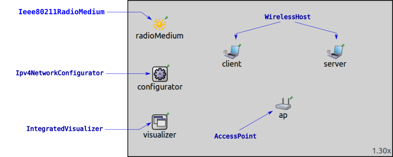
It contains two WirelessHost’s named client and server,
and an AccessPoint.
There are two configurations in omnetpp.ini: NonQos and Qos.
The physical layer and traffic settings are specified in the NonQos configuration.
The hosts are configured to use a PHY data rate of 54 Mbps.
The client host is configured to send UDP packets to the server host.
Each UDP application sends packets to a different UDP port, corresponding to the access categories.
Here is the port configuration in omnetpp.ini:
*.client.numApps = 4
*.client.app[*].typename = "UdpBasicApp"
*.client.app[*].destAddresses = "server"
*.client.app[*].startTime = 1.0s+sendInterval*index/4
*.client.app[*].stopTime = 6.0s
*.client.app[0].destPort = 21           # background priority
*.client.app[1].destPort = 80           # best effort priority
*.client.app[2].destPort = 4000         # video priority
*.client.app[3].destPort = 5000         # voice priority
*.client.app[0].packetName = "background"
*.client.app[1].packetName = "best effort"
*.client.app[2].packetName = "video"
*.client.app[3].packetName = "voice"
The server hosts have four UdpSink applications, which receive the packets on the different ports:
*.server.numApps = 4
*.server.app[*].typename = "UdpSink"
*.server.app[0].localPort = 21          # background priority, 1
*.server.app[1].localPort = 80          # best effort, 0
*.server.app[2].localPort = 4000        # video, 5
*.server.app[3].localPort = 5000        # voice, 6
The traffic configuration is the following:
# background - 24Mbps
*.client.app[0].messageLength = 900B
*.client.app[0].sendInterval = normal(300us,10us)

# best effort - 28.8Mbps
*.client.app[1].messageLength = 900B
*.client.app[1].sendInterval = normal(250us,10us)

# video - 5Mbps
*.client.app[2].messageLength = 600B
*.client.app[2].sendInterval = normal(1ms,10us)

# voice - 100kbps
*.client.app[3].messageLength = 125B
*.client.app[3].sendInterval = normal(10ms,10us)
The Qos configuration extends the NonQos configuration. It enables QoS,
and sets the classifier type:
[Config Qos]
extends = NonQos

*.*.wlan[*].mac.qosStation = true
*.*.wlan[*].classifier.typename = "QosClassifier"
Results
We’ll look at three measures one by one: end-to-end delay, jitter, and throughput.
End-to-End Delay
Here is the plot of the end-to-end delay of received packets in the non-QoS case:
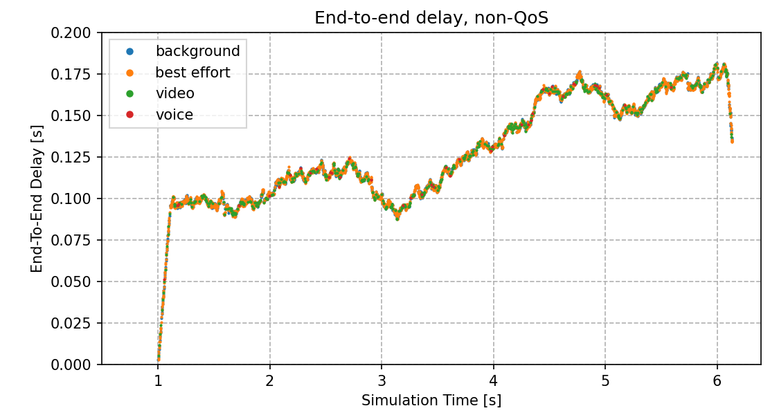
The end-to-end delay vector data points for the four access categories run together because the MAC treats all packets the same (there is one packet queue).
The curve is straight and steep at the beginning, due to the queue being filled up.
When it is already filled up, the delay starts to fluctuate. The UDP applications
generate more traffic than the channel can carry, thus the queue stays filled up,
and packets are dropped. Note that dropped packets are not indicated on the charts,
as we’re plotting UDP packets received by server.
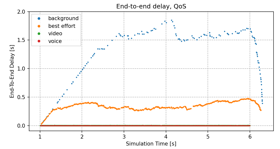
In the QoS case, as expected, the higher priority access categories (video, voice) have lower delay, because they are often sent before the lower priority ones (they are more likely to be sent first.)
The best effort category is prioritized over the background priority; the best effort has lower delay. At around 1.3 seconds, the best effort queue runs out of the earliest packets, and the delay starts to fluctuate. The same thing happens to the background queue at around 2.5 seconds. It takes more time for the background priority curve to start to fluctuate because the background frames are sent more sporadically, so that it takes more time for the early packets in the queue to be sent.
The average end-to-end delay for the different access categories are summarized in the following table (approximately):
non-Qos |
QoS |
|
|---|---|---|
background |
128 ms |
1300 ms |
best effort |
128 ms |
345 ms |
video |
128 ms |
2 ms |
voice |
128 ms |
1 ms |
In the QoS case, the video and voice priority delay is markedly improved compared to the non-QoS case. On the other hand, the background and best effort delay increased substantially.
Jitter
Let’s take a look at jitter:
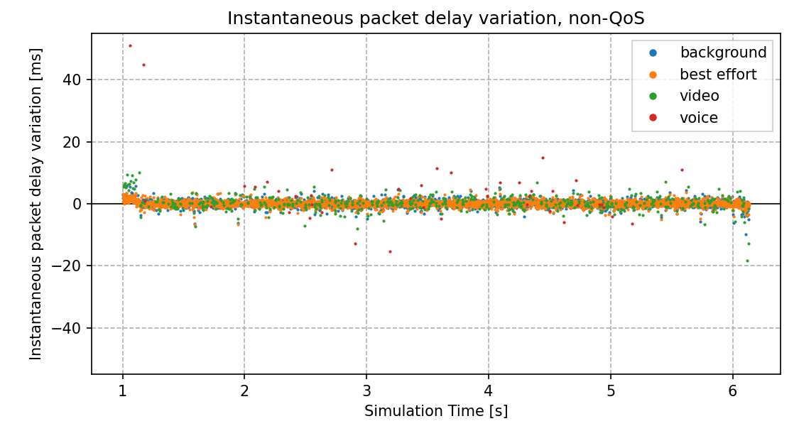
In the non-QoS case, the jitter data points are scattered with the same pattern for all four traffic categories.
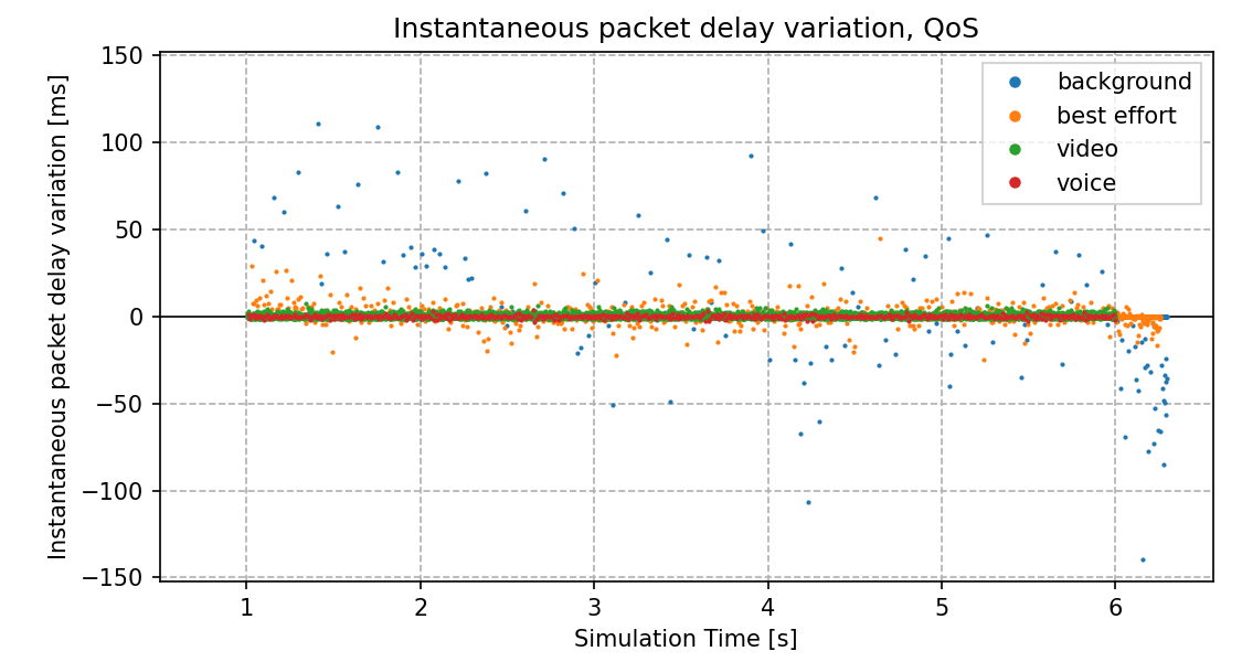
In the QoS case, the jitter is lower for the video and voice categories (lowest for voice), and higher for background and best effort. Also, the background and best effort data points are more scattered than the higher priority ones. The jitter for the lower priority categories decreases at around 6 seconds when the higher priority traffic stops.
Here are the jitter charts on the same scale (slightly zoomed in):
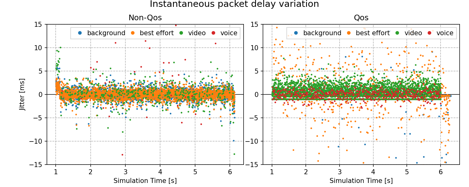
The following table summarizes the average jitter for the different access categories (approximately):
non-Qos |
QoS |
|
|---|---|---|
background |
30 ms |
440 ms |
best effort |
30 ms |
73 ms |
video |
30 ms |
1.1 ms |
voice |
30 ms |
0.6 ms |
As with the delay, the jitter is improved in the QoS case for video and voice, and worse for background and best effort.
Let us spend a minute on explaining an artifact in the QoS jitter plot, namely some data points forming horizontal lines. Here is a relevant part of the plot, zoomed in:

Some jitter data points of best effort and video form two horizontal lines. The best effort line is at -0.25 ms; the video line is at -1 ms. The reason for these data points is that sometimes, packets belonging to the same access category are sent consecutively. The packets are generated every 0.25 and 1 ms, but it takes a few microseconds to transmit a frame, thus the consecutive packets arrive at the receiver at the same time (a few microseconds apart). This results in the -0.25 ms and -1 ms jitter.
There is no horizontal line for background because it is low priority and packets don’t have the chance to be sent consecutively. Also, there is no horizontal line for voice, because voice packets are generated infrequently and they are high priority; a voice packet gets transmitted before the next one is generated.
Throughput
Let’s see the throughput:
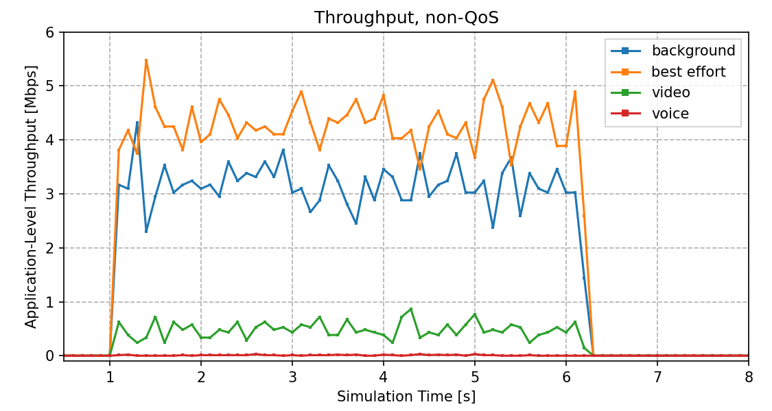
In the non-QoS case, the throughput for the four applications is more or less proportional to their generated traffic (more for background and best effort, less for video and even less for voice). However, none of the access categories can send data at the rate the application is generating it because all four categories have the same chance for gaining access to the channel, and the channel is saturated.
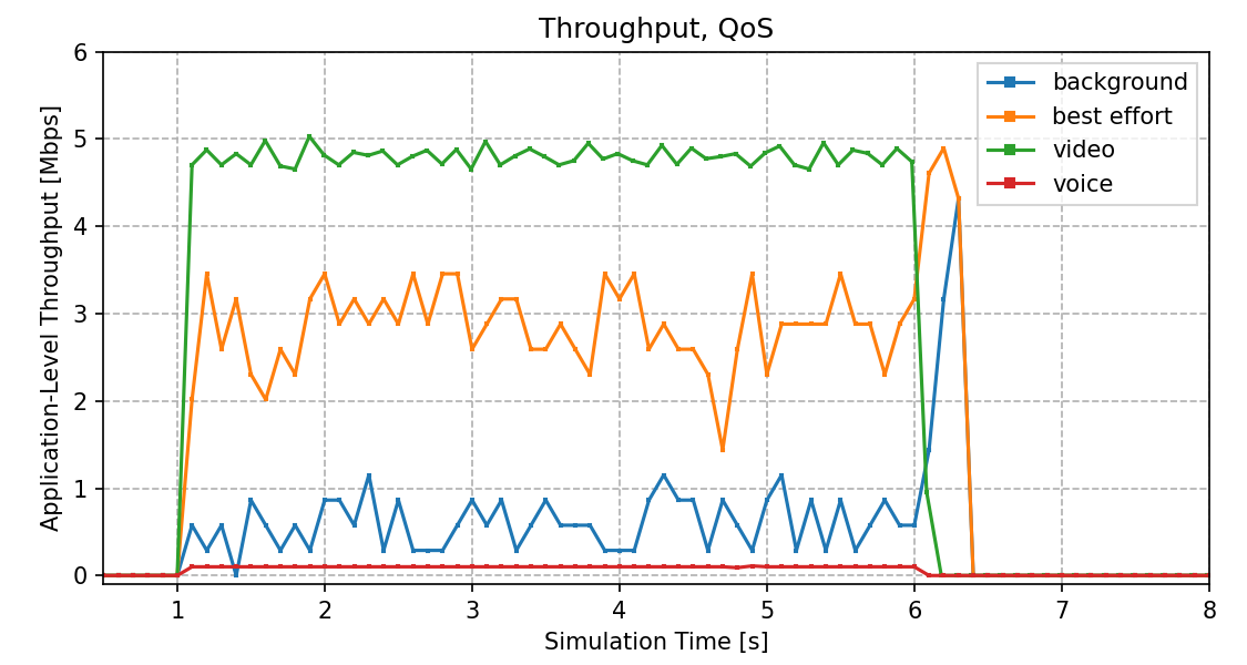
In the QoS case, throughput for the video and voice categories can reach their nominal bitrate. The throughput for the background and best effort categories is lower while the high priority ones have data to send, and increases just a bit when the high priority traffic stops (there are still some packets left in the background and best effort queues).
The bitrate of video and voice is lower than the others, but the others generate enough traffic to saturate the channel on their own. Thus the video and voice categories need QoS to sustain nominal throughput.
Sources: omnetpp.ini, QosShowcase.ned
Try It Yourself
If you already have INET and OMNeT++ installed, start the IDE by typing
omnetpp, import the INET project into the IDE, then navigate to the
inet/showcases/wireless/qos folder in the Project Explorer. There, you can view
and edit the showcase files, run simulations, and analyze results.
Otherwise, there is an easy way to install INET and OMNeT++ using opp_env, and run the simulation interactively.
Ensure that opp_env is installed on your system, then execute:
$ opp_env run inet-4.6 --init -w inet-workspace --install --build-modes=release --chdir \
   -c 'cd inet-4.6.*/showcases/wireless/qos && inet'
This command creates an inet-workspace directory, installs the appropriate
versions of INET and OMNeT++ within it, and launches the inet command in the
showcase directory for interactive simulation.
Alternatively, for a more hands-on experience, you can first set up the workspace and then open an interactive shell:
$ opp_env install --init -w inet-workspace --build-modes=release inet-4.6
$ cd inet-workspace
$ opp_env shell
Inside the shell, start the IDE by typing omnetpp, import the INET project,
then start exploring.
Discussion
Use this page in the GitHub issue tracker for commenting on this showcase.