Step 8. Configuring a mixed wired/wireless network
Goals
This step demonstrates routing table configuration in a mixed wired/wireless network. This step consists of two parts:
Part A: Determining members of wireless networks with the
<wireless>elementPart B: Determining members of wireless networks by SSID
Part A: Using the <wireless> element
The configurator assumes that interfaces of wireless nodes in the same wireless network can reach each other directly. It can determine which nodes belong to a wireless network in two ways:
It looks at the
defaultSsidparameter in nodes’ agent submodule. Nodes with the same SSID are assumed to be in the same wireless network.Members of wireless networks can be specified by the
<wireless>element in the XML configuration. In the<wireless>element, thehostsandinterfacesselector attributes can be used to specify members.
Note that nodes need to use the same radio medium module to be in the same wireless network.
Configuration
This step uses the ConfiguratorC network defined in
ConfiguratorC.ned. The network is
displayed on the following image.
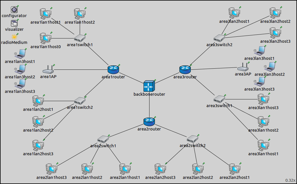
The ConfiguratorC network extends ConfiguratorB by adding two
wireless LANs, area1lan3 and area3lan3. The additional LANs
consist of an AccessPoint and three WirelessHosts.
The default SSID setting of all wireless nodes is "SSID". By
default, the configurator would put them in the same wireless network,
and assume that they can all reach each other directly. This would be
reflected in the routes, hosts in area1lan3 would reach hosts in
area3lan3 directly. This is obviously wrong because they are out of
range of each other. The two LANs need to be in two different wireless
networks.
Here is the configuration for this step in omnetpp.ini:
[Config Step8A]
sim-time-limit = 100s
network = ConfiguratorC
description = "Mixed wired/wireless network configuration - using <wireless> attribute"

*.configurator.config = xmldoc("step8a.xml")

*.area1lan3host2.numApps = 1
*.area1lan3host2.app[0].typename = "PingApp"
*.area1lan3host2.app[*].destAddr = "area3lan3host2"

# Wireless settings
*.*.wlan[*].bitrate = 54Mbps

# visualizer settings
*.visualizer.routingTableVisualizer.displayRoutingTables = true
*.visualizer.routingTableVisualizer.destinationFilter = "area3lan3*"

*.visualizer.routingTableVisualizer.lineShift = 0
A wireless host in area 1 is configured to ping a wireless host in area 3, which helps in visualizing routes.
There is a setting in the General configuration pertaining to
wireless networks: the control bit rate of all wireless nodes is set to
54 Mbps for faster ACK transmissions.
[General]
description = "(abstract)"

# Configurator settings
*.configurator.dumpAddresses = true
*.configurator.dumpTopology = true
*.configurator.dumpLinks = true
*.configurator.dumpRoutes = true

# Routing settings
*.*.ipv4.arp.typename = "GlobalArp"
*.*.ipv4.routingTable.netmaskRoutes = ""

# Visualizer settings
*.visualizer.interfaceTableVisualizer.displayInterfaceTables = true
*.visualizer.interfaceTableVisualizer.nodeFilter = "not (*switch* or *Switch* or *AP*)"
The XML configuration in step8a.xml is the following:
<config>
	<interface hosts="area1lan1*" address="10.1.1.x" netmask="255.255.255.x"/>
	<interface hosts="area1lan2*" address="10.1.2.x" netmask="255.255.255.x"/>
	<interface hosts="area1lan3*" address="10.1.3.x" netmask="255.255.255.x"/>
	<interface hosts="area2lan1*" address="10.2.1.x" netmask="255.255.255.x"/>
	<interface hosts="area2lan2*" address="10.2.2.x" netmask="255.255.255.x"/>
	<interface hosts="area3lan1*" address="10.3.1.x" netmask="255.255.255.x"/>
	<interface hosts="area3lan2*" address="10.3.2.x" netmask="255.255.255.x"/>
	<interface hosts="area3lan3*" address="10.3.3.x" netmask="255.255.255.x"/>
	<interface hosts="backbonerouter" towards="area1router" address="10.1.3.x" netmask="255.255.255.x"/>
	<interface hosts="backbonerouter" towards="area2router" address="10.2.3.x" netmask="255.255.255.x"/>
	<interface hosts="backbonerouter" towards="area3router" address="10.3.3.x" netmask="255.255.255.x"/>
	<interface hosts="*" address="10.x.x.x" netmask="255.255.255.x"/>
	<wireless hosts="area1lan3* area1AP"/>
	<wireless hosts="area3lan3* area3AP"/>
</config>
The XML configuration uses the same hierarchical addressing scheme as in Step 7. The two wireless LANs are specified to be in separate wireless networks. Note that the wireless interfaces of the access points also belong to the wireless networks.
Results
The addresses and routes are indicated in the following image. Routes
leading towards hosts area3lan3 are visualized.
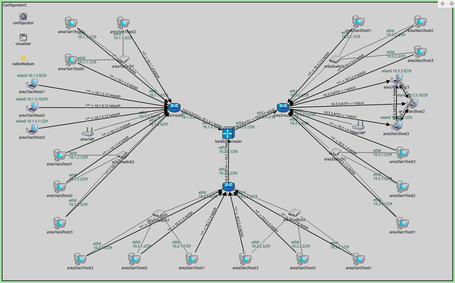
Wireless hosts connect to the router through the access points. The access points are L2 devices, similar to switches, so they are transparent for the routing table visualizer arrows. Wireless hosts get associated with their corresponding access points before they can communicate with the rest of the network.
On the following video, area1lan3host2 pings area3lan3host2.
Transmissions are sent to all wireless nodes, but only those in
communication range can receive them correctly (i.e. nodes in the same
LAN).
The following image shows how the routes would look like if the XML configuration didn’t
contain the <wireless> elements:
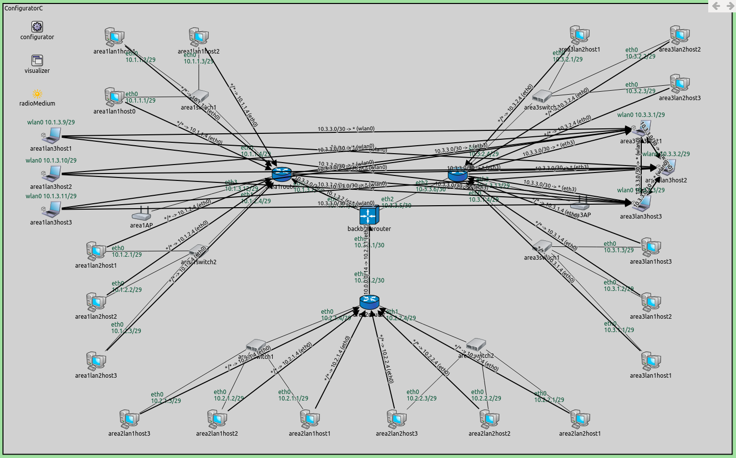
There are no routes visualized between the backbonerouter and
area3router, because routes towards area3lan3 go via
area1router. Area3lan3 can be reached from the
backbonerouter in two ways:
area1router→area1AP→area3lan3(area1APreachesarea3lan3directly since they are assumed to be in the same wireless network)area3router→area3AP→area3lan3
In both ways, area3lan3 is two hops away from the
backbonerouter. Routes are configured according to hop count, and
the configurator chose the first way.
Part B - Using SSID
In this part, the SSID is used to put the two wireless LANs in two different wireless networks.
Configuration
The configuration for this part extends Part A. The configuration in omnetpp.ini is the following:
[Config Step8B]
sim-time-limit = 100s
extends = Step8A
description = "Mixed wired/wireless network configuration - using SSID"

*.configurator.config = xmldoc("step8b.xml")

*.area1AP.wlan[*].mgmt.ssid = "area1"
*.area3AP.wlan[*].mgmt.ssid = "area3"

*.area1lan3*.wlan[*].agent.defaultSsid = "area1"
*.area3lan3*.wlan[*].agent.defaultSsid = "area3"
The XML configuration in step8b.xml (displayed below) is the same as the
XML configuration for Part A, except there are no <wireless>
elements that defined wireless networks. They are not needed because
different SSIDs are configured for the members of the two wireless LANs.
<config>
	<interface hosts="area1lan1*" address="10.1.1.x" netmask="255.255.255.x"/>
	<interface hosts="area1lan2*" address="10.1.2.x" netmask="255.255.255.x"/>
	<interface hosts="area1lan3*" address="10.1.3.x" netmask="255.255.255.x"/>
	<interface hosts="area2lan1*" address="10.2.1.x" netmask="255.255.255.x"/>
	<interface hosts="area2lan2*" address="10.2.2.x" netmask="255.255.255.x"/>
	<interface hosts="area3lan1*" address="10.3.1.x" netmask="255.255.255.x"/>
	<interface hosts="area3lan2*" address="10.3.2.x" netmask="255.255.255.x"/>
	<interface hosts="area3lan3*" address="10.3.3.x" netmask="255.255.255.x"/>
	<interface hosts="backbonerouter" towards="area1router" address="10.1.3.x" netmask="255.255.255.x"/>
	<interface hosts="backbonerouter" towards="area2router" address="10.2.3.x" netmask="255.255.255.x"/>
	<interface hosts="backbonerouter" towards="area3router" address="10.3.3.x" netmask="255.255.255.x"/>
	<interface hosts="*" address="10.x.x.x" netmask="255.255.255.x"/>
</config>
Results
The results are the same as in the previous part. The two wireless LANs are considered to be different wireless networks.
Sources: omnetpp.ini,
ConfiguratorC.ned
Discussion
Use this page in the GitHub issue tracker for commenting on this tutorial.