IEEE 802.11 Throughput
Goals
This example analyzes how application-level throughput changes as a function of nominal bitrate in an 802.11g network.
4.6The model
Application-level throughput
802.11 modes are denoted by the nominal data bitrate (e.g. 54 Mbps). However, the bitrate available for an application is less than the nominal bitrate because of protocol overhead like preambles, physical and MAC headers, TCP and IP headers, interframe spaces, and backoff periods. In this model, the actual application-level throughput is measured.
Configuration
The network contains two WirelessHost’s, at a distance of 1 meter, one of them acting as a traffic source, the other one as a traffic sink. The source host sends a UDP stream to the destination host in ad-hoc mode. The simulation is run with a small packet size of 100 bytes, 1000 bytes, and the default maximum unfragmented packet size in 802.11, 2236 bytes. (The maximum transfer unit in 802.11 by default is 2304 bytes, which corresponds to 2236 bytes of application data.) The simulation will be run several times, with different bitrates. The UDP application in the source host is configured to saturate the channel at all bitrates and packet sizes. There will be no packets lost in the physical layer because the hosts are close to each other, and the background noise is configured to be very low.
The parameter study iterates over the following 802.11g bitrates: 6, 9, 12, 18, 24, 36, 48, and 54 Mbps. Each simulation runs for 1 second, and the UDP throughput is averaged for this interval.
Results
Throughput measured in the simulation is compared to analytically obtained values. The application-level throughput can be calculated from the nominal bitrate and the payload size, for example, using the excel sheet here.) It takes the DIFS, data frame duration, SIFS, ACK duration, and backoff period into account. It assumes an average backoff time that is half of the minimal contention window to calculate the theoretical throughput:
throughput= 1 /frameExchangeDuration*payloadLength* 8 [bps]where
frameExchangeDuration=DIFS+backoffDuration+dataFrameDuration+SIFS+ACKFrameDurationand
backoffDuration=minContentionWindow/ 2 *slotTime
The following plot compares the computed throughput to the results of the simulation for all bitrates and both packet sizes:
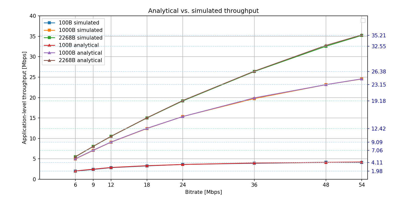
The two curves match almost exactly. The curves are not linear: throughput doesn’t increase linearly with the bitrate, especially at higher bitrates. The curve for the 2268-byte packets is nearly linear, while the curve for the 100-byte packets is not linear because the 100-byte packets have relatively more overhead due to various protocol headers, such as UDP header and 802.11 MAC header. Also, faster bitrates have more overhead. For example, with 1000-byte packets, at 6 Mbps the application-level throughput is 5 Mbps (16% overhead), whereas at 54 Mbps it is only about 24.5 Mbps (54% overhead). Faster modes only transmit the MAC header and content part of frames at higher bitrates, the preamble, physical header, interframe spaces, and backoff stay the same, thus the overhead gets larger as the bitrate increases.
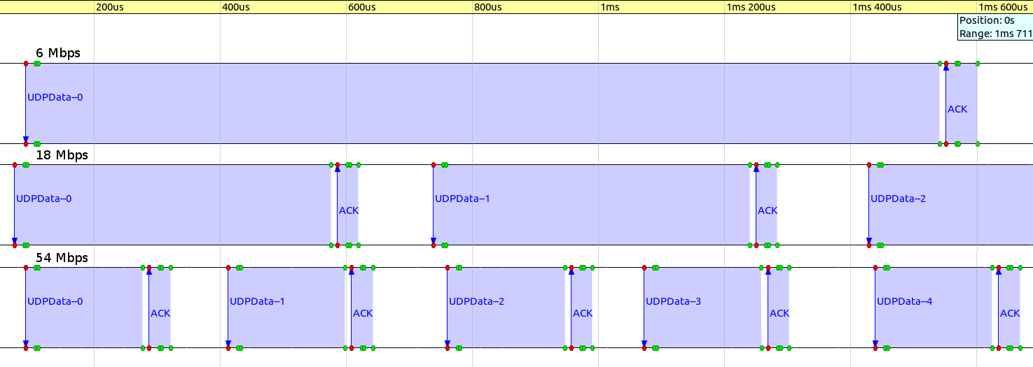
The following sequence chart excerpt illustrates overhead increasing with bitrate. It shows frame exchanges for 1000-byte UDP packets, with bitrates of 6, 18, and 54 Mbps, on the same linear timescale. One can see how the proportion of data parts shrinks compared to the duration of the frame exchange as bitrates increase.
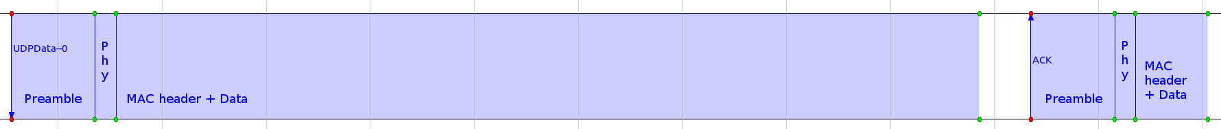
The following sequence chart illustrates the relative sizes of the preamble, physical header, and data part of a 54 Mbps frame exchange. The preamble and the physical header have the same duration regardless of the bitrate, further increasing overhead at higher bitrates.
There are techniques that increase application-level throughput by reducing overhead. For example, in 802.11n, overhead at high bitrates is reduced by using block acknowledgment and frame aggregation. When block acknowledgment is used, multiple data frames can be acknowledged with a single block acknowledgment frame (instead of ACKing each data frame one-by-one.) Frame aggregation allows multiple data frames to be sent following a preamble and a physical header in a single transmission. Recent versions of the INET Framework support these 802.11 features, but they are out of scope for this simulation example.
Sources: omnetpp.ini, Throughput.ned
Further information
More information can be found in the INET Reference.
Try It Yourself
If you already have INET and OMNeT++ installed, start the IDE by typing
omnetpp, import the INET project into the IDE, then navigate to the
inet/showcases/wireless/throughput folder in the Project Explorer. There, you can view
and edit the showcase files, run simulations, and analyze results.
Otherwise, there is an easy way to install INET and OMNeT++ using opp_env, and run the simulation interactively.
Ensure that opp_env is installed on your system, then execute:
$ opp_env run inet-4.6 --init -w inet-workspace --install --build-modes=release --chdir \
   -c 'cd inet-4.6.*/showcases/wireless/throughput && inet'
This command creates an inet-workspace directory, installs the appropriate
versions of INET and OMNeT++ within it, and launches the inet command in the
showcase directory for interactive simulation.
Alternatively, for a more hands-on experience, you can first set up the workspace and then open an interactive shell:
$ opp_env install --init -w inet-workspace --build-modes=release inet-4.6
$ cd inet-workspace
$ opp_env shell
Inside the shell, start the IDE by typing omnetpp, import the INET project,
then start exploring.
Discussion
Use this page in the GitHub issue tracker for commenting on this showcase.