Step 13. Configuring a more accurate path loss model
Goals
By default, the medium uses the free-space path loss model, which assumes a line-of-sight path, with no obstacles nearby to cause reflection or diffraction. Since our wireless hosts move on the ground, a more accurate path loss model would be the two-ray ground reflection model that calculates with one reflection from the ground.
The model
It has been mentioned that ScalarRadioMedium relies on various
subcomponents for computing path loss, obstacle loss, and background
noise, among others. Installing the two-ray ground reflection model is
just a matter of changing its pathLossType parameter from the
default FreeSpacePathLoss to TwoRayGroundReflection. (Further
options include RayleighFading, RicianFading,
LogNormalShadowing, and some others.)
The two-ray ground reflection model uses the altitudes of the transmitter and the receiver antennas above the ground as input. To compute the altitude, we need the hosts’ (x,y,z) positions and the ground’s elevation at those points. The z coordinates of hosts have been set to 1.7m in an earlier step. The ground’s elevation is defined by the ground model, which is part of the physical environment model.
In this model, we’ll use FlatGround for the ground model, and specify it
to the physicalEnvironment module. (Note that we added
physicalEnvironment to the network when we introduced obstacles.)
The ground’s elevation is the elevation parameter of FlatGround.
We set this parameter to 0m.
[Config Wireless13]
description = Configuring a more accurate pathloss model
extends = Wireless12

*.physicalEnvironment.ground.typename = "FlatGround"
*.physicalEnvironment.ground.elevation = 0m

*.radioMedium.pathLoss.typename = "TwoRayGroundReflection"
Results
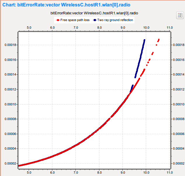
The image below shows the bit error rate of host R1’s radio as a function of time. The bit error rate is shown when free space path loss is used, and when using the two-ray ground reflection model. The interval shown here corresponds to the time in the simulation when host R1 is not cut off from host A by the wall anymore, and also still in communication range of host A and B. In the interval that is shown, from around 5 seconds to 11 seconds, the distance between host R1 and hosts A and B is increasing, which results in an increase in the bit error rate as well. There is no significant difference between the free space propagation path loss and the two-ray ground reflection path loss at first. The two curves separate towards the end of the displayed interval. As expected, in the case of the two-ray ground reflection model, the bit error rate is greater.
Number of packets received by host B: 679
Sources: omnetpp.ini,
WirelessC.ned
Discussion
Use this page in the GitHub issue tracker for commenting on this tutorial.