IEEE 802.11 Handover
Goals
This simulation demonstrates the handover process between two access points (APs) in an 802.11 wireless LAN operating in infrastructure mode. The demonstration highlights the various steps involved in the handover, including beacon transmission, active scanning, authentication, and association. The goal of this simulation is to illustrate the realism and accuracy of the INET Framework in simulating real-world wireless network scenarios.
4.0The Model
In 802.11 infrastructure mode, wireless hosts need to be associated with an access point before data exchange can occur. The hosts can find an access point in two ways. One is active scanning, where hosts transmit Probe Request frames, and the APs reply to them with Probe Response frames. The other is passive scanning, where hosts locate APs by receiving their broadcast Beacon frames. APs emit Beacon frames periodically, announcing their presence (unless configured to be hidden). In this simulation, the host uses active scanning.
When the host has discovered the available APs, it decides which one to join. When the host wants to join an AP, it initiates an authentication frame exchange with the AP. Following successful authentication, the host starts the association frame exchange. During the association process, they agree on the encryption type and other 802.11 capabilities to use, and the AP grants the host access to the network. When the association is complete, data exchange can begin.
The example simulation will use the following network:
The network contains two APs placed 400 meters apart, and a wireless host. The two access points are set to use channels 2 and 3. The host is configured to actively scan channels 0 through 4. During the simulation, the host will move out of range of one access point and into the range of the other. In this model, when scanning for APs, the host will always choose the one with the strongest signal. In this simulation, there are no applications configured in the host to send or receive data, so we will not be able to observe data exchange. The host will just be associated to the APs, and keep receiving beacon frames.
Results
The following animation shows what happens when the simulation is run:
At the beginning of the simulation, the host starts to scan the channels, looking for an access point to associate with. This process is started by the host’s agent module, as it is set to active scanning. (In INET, an 802.11 interface consists of a MAC module, a management module that deals with management frames, and an agent module that initiates scanning, association, and other high-level actions.)
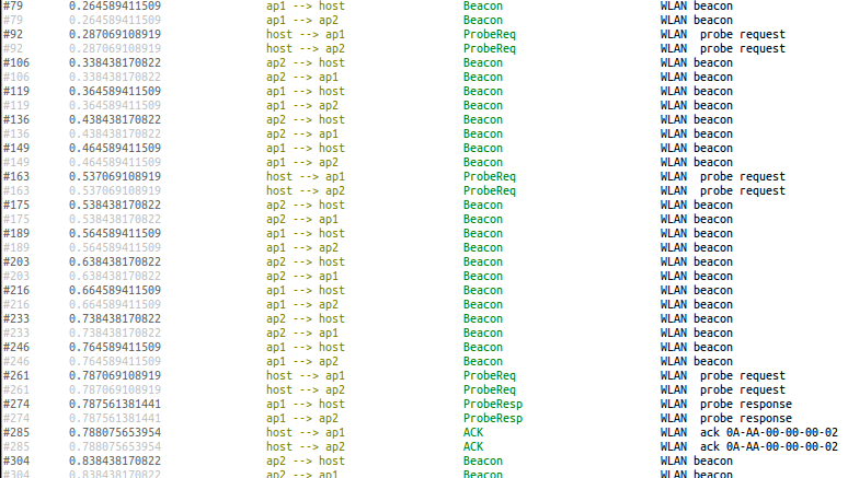
During the scanning process, the host sends a Probe Request frame in each channel starting from channel 0, until it receives a Probe Response. As AP1 is on channel 2, the host sends out three Probe Requests before it gets a Probe Response. This frame exchange is shown in the following packet log.
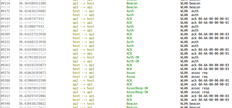
When the host gets the Probe Response, it initiates the authentication process. After that is completed, it starts the association process. The authentication process consists of several steps. When it becomes associated with AP1, a text bubble appears at the host indicating that it is associated with the AP. The authentication and association processes are shown in the packet log below.
This animation shows the handover.
The dotted arrows indicate recent successful physical layer transmissions. In this example, they will be used to visualize that the host is associated with an AP. The APs send out beacon frames periodically, which is now configured to be 100 ms. These frames are received by the host, which constantly reinforces the physical link visualizer arrows. When the host is in range of AP1, the only communication is the host receiving AP1’s beacon frames. This reception is indicated by the dotted arrow, which only goes from the AP to the host.
The host remains associated with AP1 as long as it is within communication range, even though it gets into the communication range of AP2 after a while (when it enters the area where the two APs’ communication range circles overlap.) As it leaves AP1’s range, the host detects that it no longer receives AP1’s beacon frames. A text bubble appears at the host indicating that it has lost the beacon. The scanning process is restarted by the host’s agent module. This is triggered when several consecutive beacon frames are not received.
This time it takes four Probe Request frames to get a response because AP2 is on channel 3.
The host is handed over to AP2 using the authentication and association process discussed earlier. It will remain associated with AP2 until it leaves AP2’s communication range.
The host’s mgmt module contains a variable that indicates which
access point the host is associated with.
The mgmt modules of access points maintain a list of hosts that are
associated with them.
Sources: omnetpp.ini, HandoverShowcase.ned
Try It Yourself
If you already have INET and OMNeT++ installed, start the IDE by typing
omnetpp, import the INET project into the IDE, then navigate to the
inet/showcases/wireless/handover folder in the Project Explorer. There, you can view
and edit the showcase files, run simulations, and analyze results.
Otherwise, there is an easy way to install INET and OMNeT++ using opp_env, and run the simulation interactively.
Ensure that opp_env is installed on your system, then execute:
$ opp_env run inet-4.0 --init -w inet-workspace --install --chdir \
   -c 'cd inet-4.0.*/showcases/wireless/handover && inet'
This command creates an inet-workspace directory, installs the appropriate
versions of INET and OMNeT++ within it, and launches the inet command in the
showcase directory for interactive simulation.
Alternatively, for a more hands-on experience, you can first set up the workspace and then open an interactive shell:
$ opp_env install --init -w inet-workspace inet-4.0
$ cd inet-workspace
$ opp_env shell
Inside the shell, start the IDE by typing omnetpp, import the INET project,
then start exploring.


