Displaying IP Addresses and Other Interface Information
Goals
In complex network simulations, it is often useful to display per-interface information, such as IP addresses, interface names, etc., either above node icons or on the links. This helps in verifying that the network configuration matches expectations, especially when automatic address assignment is used (e.g. using the Ipv4NetworkConfigurator). Although this information can be accessed through the object inspector panel in the GUI, it can be tedious and difficult to get an overview.
This showcase presents two example simulations that demonstrate the visualization of IP addresses and other interface information. The first simulation shows the display of the information with the default settings of the visualizer, while the second one focuses on the advanced features.
4.6About the visualizer
The InterfaceTableVisualizer module (included in the network as part
of IntegratedCanvasVisualizer) displays data about network nodes’
interfaces. (Interfaces are contained in interface tables, hence the
name.) By default, the visualization is turned off. When it is enabled
using the displayInterfaceTables parameter, the default is that
interface names, IP addresses, and netmask length are displayed, above
the nodes (for wireless interfaces) and on the links (for wired
interfaces). By clicking on an interface label, details are displayed in
the inspector panel.
The visualizer has several configuration parameters. The format
parameter specifies what information is displayed about interfaces. It
takes a format string, which can contain the following directives:
%N: interface name%4: IPv4 address%6: IPv6 address%n: network address. This is either the IPv4 or the IPv6 address%l: netmask length%M: MAC address%\\: conditional newline for wired interfaces. (Note that the backslash needs to be doubled, due to escaping.)%s: thestr()functions for the interface entry class
The default format string is "%N %\\%n/%l", i.e. interface name, IP
address, and netmask length.
The set of visualized interfaces can be selected with the configurator’s
nodeFilter and interfaceFilter parameters. By default, all
interfaces of all nodes are visualized, except for loopback addresses
(the default for the interfaceFilter parameter is "not lo\*".)
It is possible to display the labels for wired interfaces above the node
icons, instead of on the links. This selection can be done by setting the
displayWiredInterfacesAtConnections parameter to false.
There are also several parameters for styling, such as color and font selection.
Enabling the visualization
The first example demonstrates the default operation of the visualizer. The simulation uses the following network:
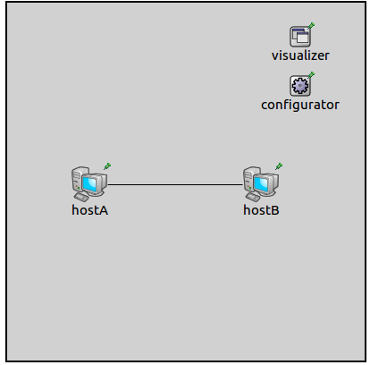
The network contains two connected StandardHost’s. IP addresses are auto-assigned by an Ipv4NetworkConfigurator module.
We enable visualization by the following configuration line:
*.visualizer.interfaceTableVisualizer.displayInterfaceTables = true
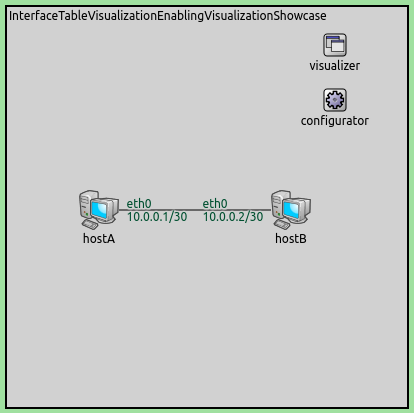
The interface names and the assigned IP addresses are displayed at the gates where the interfaces are connected. When the simulation is run, the network looks like the following:
More examples
In the following example, we’d like to show the usefulness of this
visualizer in a dynamic scenario, as well as demonstrate filtering. The
simulation can be run by choosing the AdvancedFeatures configuration
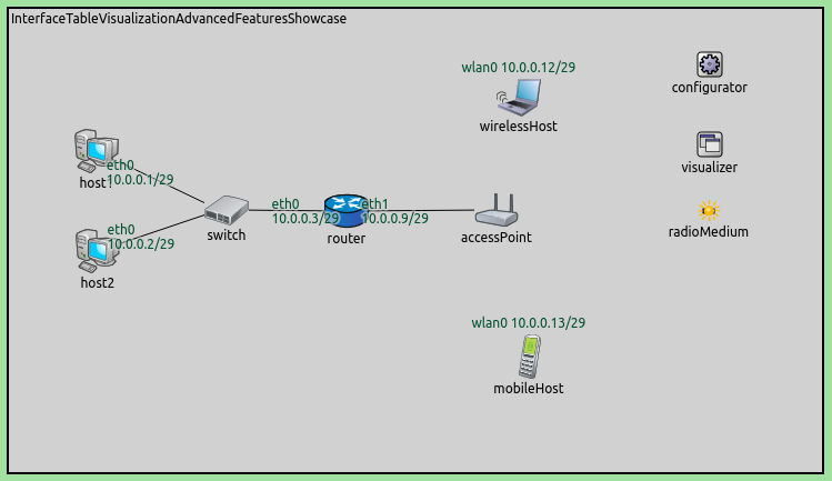
from the ini file. It uses the following network:
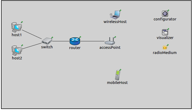
It contains two StandardHost’s connected to an EthernetSwitch. The switch is connected to a Router, which is connected to an AccessPoint. There is a WirelessHost and an AdhocHost near the access point. They will obtain their addresses from the router via DHCP. We would like to see IP addresses appear above the hosts when they get their addresses.
We would like to hide the display of loopback addresses and the unspecified address, so we set the following filter for the visualizer:
*.visualizer.interfaceTableVisualizer.interfaceFilter = 'not lo* and not ipv4Address =~ "<unspec>"'
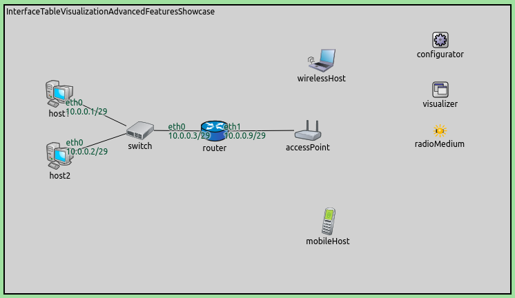
Initially, the addresses of the wired interfaces of host1, host2,
and the router are visualized. The wireless hosts have unspecified
addresses, thus no interface indicator is displayed. The network looks
like this:
When the wireless hosts have been associated with the access point and received their addresses from the DHCP server, the new addresses will be displayed. The network will look like this:
Sources: omnetpp.ini, InterfaceTableVisualizationShowcase.ned
Further information
For more information, refer to the InterfaceTableVisualizer NED documentation.
Try It Yourself
If you already have INET and OMNeT++ installed, start the IDE by typing
omnetpp, import the INET project into the IDE, then navigate to the
inet/showcases/visualizer/canvas/interfacetable folder in the Project Explorer. There, you can view
and edit the showcase files, run simulations, and analyze results.
Otherwise, there is an easy way to install INET and OMNeT++ using opp_env, and run the simulation interactively.
Ensure that opp_env is installed on your system, then execute:
$ opp_env run inet-4.6 --init -w inet-workspace --install --build-modes=release --chdir \
   -c 'cd inet-4.6.*/showcases/visualizer/canvas/interfacetable && inet'
This command creates an inet-workspace directory, installs the appropriate
versions of INET and OMNeT++ within it, and launches the inet command in the
showcase directory for interactive simulation.
Alternatively, for a more hands-on experience, you can first set up the workspace and then open an interactive shell:
$ opp_env install --init -w inet-workspace --build-modes=release inet-4.6
$ cd inet-workspace
$ opp_env shell
Inside the shell, start the IDE by typing omnetpp, import the INET project,
then start exploring.
Discussion
Use this page in the GitHub issue tracker for commenting on this showcase.