Step 5. Manually overriding individual routes
Goals
Automatic configuration can fill the routing tables correctly, but sometimes the user might want to manually override some of the routes. This step consists of two parts:
In Part A we will override the routes to just one specific host
In Part B we will override routes to a set of hosts
Part A - Overriding routes to a specific host
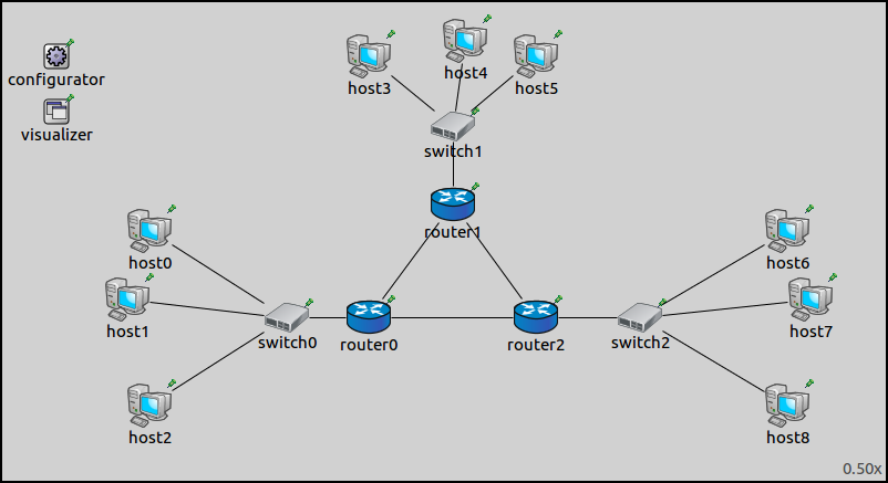
Both parts in this step use the ConfiguratorA network (displayed
below), just as in the previous steps. In this part, we will override the
routes going from the subnet of router0 to host7. With the
automatic configuration, packets from router0’s subnet would go
through router2 to reach host7 (as in the previous step.) We
want them to go through router1 instead.
Configuration
The configuration in omnetpp.ini is the following:
[Config Step5A]
sim-time-limit = 500s
extends = Step4
description = "Manually overriding individual routes - route to a specific host"

*.configurator.config = xmldoc("step5a.xml")

*.host0.numApps = 1
*.host0.app[0].typename = "PingApp"
*.host0.app[*].destAddr = "host6"
*.host0.app[*].startTime = 0.6s
A ping application is added to host0, in addition to the one in
host1 added in Step 4. The new app in host0 pings host6 to
demonstrate that only packets sent to host7 are affected by the
route override.
For the routes to go through router1, the routing table of
router0 has to be altered. The new rules should dictate that packets
with the destination of host7 (10.0.0.35) should be routed towards
router2. The XML configuration in step5a.xml is the following:
<config>
	<interface hosts="**" address="10.x.x.x" netmask="255.x.x.x"/>
	<route hosts="router0" destination="10.0.0.35" netmask="255.255.255.255" gateway="10.0.0.18" interface="eth1" metric="0"/>
</config>
The <route> element describes a routing table entry for one or more
nodes in the network. The hosts optional selector attribute
specifies which hosts’ routing tables should be affected. There are five
additional optional parameter attributes. These are the same as in real
life routing tables: address, netmask, gateway,
interface, metric.
The <route> element in this XML configuration adds the following
rule to router0’s routing table: Packets with the destination of
10.0.0.35/32 should use the interface eth1 and the gateway 10.0.0.18
(router1.) The concrete IP addresses were obtained by setting up the
network without the <route> element first and inspecting the
result.
Caveats
First, note that adding a route manually does not erase the original route. Therefore, the new route will only take effect if it is “stronger” than the automatically added one, for example, it has a longer matching prefix, better metric, or (given the previous ones are equal) occurs earlier in the routing table. Luckily, the last condition usually holds (manually added routes are added at the top), so manually added routes do take effect unless they are explicitly weaker than the original ones.
Second, note that the <route> element refers to addresses (e.g.
10.0.0.35) which were automatically assigned by the <interface>
element. It is valid to do so because the assignment of IP addresses is
deterministic, that is, given the same input, it will always produce the
same result. However, if you change the network topology, for example,
add, remove, or reorder hosts, addresses might be assigned in a different
way. The consequence may be that addresses in the <route> element no
longer exist in the modified network or they refer to different
hosts/routers than originally intended, i.e. the configuration will
silently break.
One solution to make the configuration more robust is to explicitly
assign the addresses in question, using extra <interface> elements.
(Note, however, that adding an <interface> element might also affect
the automatically assigned addresses, so it makes sense to add all
<interface> rules together at once, instead of one-by-one.) Another
solution would be to let <route> elements refer to addresses
symbolically, i.e. be able to formally express “the address of
router1’s interface that faces router0” instead of spelling out
“10.0.0.18”. However, support for such mini-language has not yet been
added to the configurator.
Results
The routing table of router0 (manually added route highlighted):
Node ConfiguratorB.router0
-- Routing table --
Destination      Netmask          Gateway          Iface            Metric
10.0.0.18        255.255.255.255  *                eth1 (10.0.0.17)      0
10.0.0.22        255.255.255.255  *                eth2 (10.0.0.21)      0
10.0.0.25        255.255.255.255  10.0.0.22        eth2 (10.0.0.21)      0
10.0.0.35        255.255.255.255  10.0.0.18        eth1 (10.0.0.17)      0
10.0.0.0         255.255.255.248  *                eth0 (10.0.0.4)       0
10.0.0.32        255.255.255.248  10.0.0.22        eth2 (10.0.0.21)      0
10.0.0.0         255.255.255.224  10.0.0.18        eth1 (10.0.0.17)      0
The routing table of router0 in the previous step had six entries.
Now it has seven, as the rule specified in the XML configuration has
been added (highlighted). This and the second to last rule both match
packets to host7, but the manually added route takes effect because
it has a longer netmask (plus it’s also earlier in the table).
The following animation depicts host1 pinging host7 and
host0 pinging host6. Routes to host7 are visualized.
Note that only routes towards host7 are diverted at router0. The
ping reply packet uses the original route between router0 and
router2. Ping packets to host6 (and back) also use the original
route.
Part B - Overriding routes to a set of hosts
In this part, we will override routes going from the subnet of hosts
0–2 to the subnet of hosts 6–8. These routes will go through
router1, just as in Part A.
Configuration
The configuration in omnetpp.ini:
[Config Step5B]
sim-time-limit = 500s
extends = Step4
description = "Manually overriding individual routes - route to a set of hosts"

*.configurator.config = xmldoc("step5b.xml")
*.configurator.optimizeRoutes = false           #! TODO: this shouldn't be here, it's here because of an error in the optimizer

*.host0.numApps = 1
*.host0.app[0].typename = "PingApp"
*.host0.app[*].destAddr = "host6"
*.host0.app[*].startTime = 0.6s
As in Part A, the routing table of router0 has to be altered, so
that packets to hosts 6–8 go towards router1. The XML configuration
in step5b.xml is as follows:
<config>
	<interface hosts="**" address="10.x.x.x" netmask="255.x.x.x"/>
	<route hosts="router0" destination="10.0.0.32" netmask="255.255.255.248" gateway="10.0.0.18" interface="eth1"/>
</config>
The <route> element specifies a routing table entry for router0.
The destination is 10.0.0.32 with netmask 255.255.255.248, which
designates the addresses of hosts 6–8. The gateway is router1’s
address, the interface is the one connected towards router1
(eth1). This rule is added to router0’s routing table in
addition to the rule added automatically by the configurator. They
match the same packets, but the parameters are different (see at the
result section below.) The manually added routes come before the
automatic ones in routing tables, their prefix length and metrics are
the same; thus, the manual ones take precedence.
Results
Here is the routing table of router0 (the manually added route
highlighted):
Node ConfiguratorB.router0
-- Routing table --
Destination      Netmask          Gateway          Iface            Metric
10.0.0.10        255.255.255.255  10.0.0.18        eth1 (10.0.0.17)      0
10.0.0.18        255.255.255.255  *                eth1 (10.0.0.17)      0
10.0.0.22        255.255.255.255  *                eth2 (10.0.0.21)      0
10.0.0.25        255.255.255.255  10.0.0.22        eth2 (10.0.0.21)      0
10.0.0.26        255.255.255.255  10.0.0.18        eth1 (10.0.0.17)      0
10.0.0.33        255.255.255.255  10.0.0.22        eth2 (10.0.0.21)      0
10.0.0.0         255.255.255.248  *                eth0 (10.0.0.4)       0
10.0.0.8         255.255.255.248  10.0.0.18        eth1 (10.0.0.17)      0
10.0.0.32        255.255.255.248  10.0.0.18        eth1 (10.0.0.17)      0
10.0.0.32        255.255.255.248  10.0.0.22        eth2 (10.0.0.21)      0
The following is the animation of host1 pinging host7 and
host0 pinging host6, similarly to Part A. Routes to host7
are visualized.
This time both packets destined to hosts 6 and 7 take the diverted route and the replies come back on the original route.
Sources: omnetpp.ini,
ConfiguratorA.ned
Discussion
Use this page in the GitHub issue tracker for commenting on this tutorial.