IEEE 802.11 Transmit Opportunity
Goals
Transmit opportunity (TXOP) is a MAC feature in 802.11, which increases throughput for high priority data by providing contention-free channel access for a period of time. This showcase demonstrates frame exchanges during a TXOP.
4.2About TXOP
TXOP is available in QoS mode as part of EDCA (Enhanced Distributed Channel Access), and it is a limited time period of contention-free channel access available to the channel-owning station. During such a period the station can send multiple frames that belong to a particular access category.
The benefit of TXOP is that it increases throughput and reduces delay of QoS data frames via eliminating contention periods between transmissions. TXOP can be used in combination with aggregation and block acknowledgement to further increase throughput.
More precisely, access categories have different channel access parameters, such as AIFS (Arbitration Interframe Spacing), duration, contention window size, and TXOP limit. In the default EDCA OFDM parameter set in the 802.11 standard, these values are set so that higher priority packets are favored (the MAC waits less before sending them, the contention window is smaller, and they can be sent in a TXOP). The default parameter set specifies a TXOP limit of approximately 3 ms for the video category, and 1.5 ms for the voice category. The background and best effort categories have a TXOP limit of 0, that is, they do not use TXOP (they can send only one MSDU before having to contend for channel access again).
A station can send frames to multiple recipients during a TXOP. In addition to QoS data frames, other frames can be exchanged in the course of the TXOP, such as ACK and BlockAckReq/BlockAck frames, and other control and management frames.
TXOP in INET
In INET, the TXOP is enabled automatically when the station is in QoS mode, i.e.
uses HCF (qosStation = true in the MAC). The TXOP limit for an access
category can be set by the txopLimit parameter in the TxopProcedure
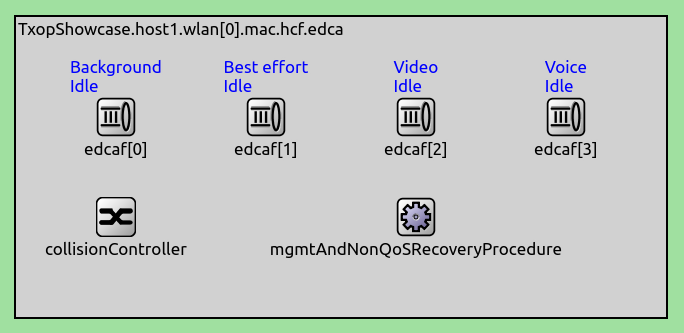
module of that access category. The module is located at hcf.edca.edcaf[*].txopProcedure
in the module hierarchy; there are four edcaf (EDCA Function) modules for the
four access categories:
The default value for the txopLimit parameter is -1 for all ACs,
meaning the 802.11 standard default values are used:
AC |
TXOP limit |
background |
0 |
best effort |
0 |
video |
3.008 ms |
voice |
1.504 ms |
The Model
Our goal is to demonstrate complex frame exchange sequences during the TXOP, such as the transmission of QoS data frames, aggregate frames, RTS and CTS frames, acks, and block acks.
In the example simulation, one host is configured to send video priority UDP packets to the other. The host sends 1200B, 3400B and 3500B packets. The RTS, aggregation and block ack thresholds are configured appropriately so that we get the following frame exchanges for demonstration:
The 1200B packets are block acked
Two of the 1200B packets can be aggregated; the aggregate frames are block acked
The 3500B packets are sent after an RTS/CTS exchange, the 3400B ones are not, both are normal acked
Thus, the list of all alternative frame sequences that can repeat during the TXOP is the following:
1200B
(1200B + 1200B) aggregated
3400B + ACK
RTS + CTS + 3500B + ACK
BlockAckReq + BlockAck
ADDBA Request + ACK
ADDBA Response + ACK
Note
In INET, frame exchange sequences are described by frame sequence (*Fs) classes.
These classes describe the order of frames allowed in a frame exchange.
For example, frame combinations possible in a TXOP are described by the
TxOpFs class. Other classes include RtsCtsFs, DataFs,
AckFs, etc.
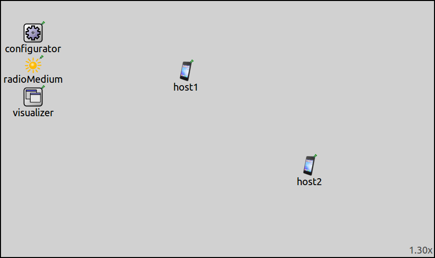
The simulation uses the following network:
It contains two AdhocHost modules, an Ipv4NetworkConfigurator, an Ieee80211ScalarRadioMedium and an IntegratedVisualizer module.
The simulation is defined in the General configuration in omnetpp.ini.
There are two UDP applications in host1, sending small (1200B) and large
(randomly 3400B or 3500B) packets to host2:
*.host1.numApps = 2
*.host1.app[*].typename = "UdpBasicApp"
*.host1.app[*].destAddresses = "host2"

*.host1.app[0].destPort = 1000
*.host1.app[0].messageLength = 1200B
*.host1.app[0].sendInterval = 0.12ms
*.host1.app[0].startTime = exponential(0.1ms)
*.host1.app[0].packetName = "small"

*.host1.app[1].destPort = 2000
*.host1.app[1].messageLength = intuniform(0,1) == 1 ? 3500B : 3400B
*.host1.app[1].sendInterval = 0.2ms
*.host1.app[1].startTime = exponential(0.1ms)
*.host1.app[1].packetName = "large"

*.host2.numApps = 2
*.host2.app[*].typename = "UdpSink"
*.host2.app[0].localPort = 1000
*.host2.app[1].localPort = 2000
QoS is enabled in both hosts, and a classifier is included. The port numbers in the classifier are configured to put all UDP packets in the voice access category:
*.host*.wlan[*].mac.qosStation = true
*.host*.wlan[*].classifier.typename = "QosClassifier"
*.host*.wlan[*].classifier.udpPortUpMap = "1000 VO 2000 VO"
IP and 802.11 fragmentation is turned off:
*.host1.wlan[*].mac.mtu = 15000B
*.host1.wlan[*].mac.hcf.originatorMacDataService.fragmentationPolicy.fragmentationThreshold = 15000B
Block acks are enabled:
*.host*.wlan[*].mac.hcf.isBlockAckSupported = true
The aggregation, RTS, and block ack thresholds are also set appropriately to produce the desired frame sequences:
**.hcf.originatorMacDataService.msduAggregationPolicy.maxAMsduSize = 3000
**.hcf.rtsPolicy.rtsThreshold = 3475B
**.hcf.originatorAckPolicy.maxBlockAckPolicyFrameLength = 3400B
Results
The following image shows frame exchanges during a TXOP, displayed on a linear-scale sequence chart:
The gap between the frames is a SIFS; the TXOP frame exchange is preceded and followed by a much longer contention period. This frame exchange sequence was recorded with 24 Mbps PHY rate. When using higher rates, more frames could fit in a TXOP, as the TXOP duration is independent of the PHY rate.
This frame sequence is just an example. Various combinations of frames can be sent during a TXOP. Observe the simulation for other combinations.
Note
The TXOP in the image is about 1.8 ms, which is longer than the 1.5 ms TXOP limit. This is due to a limitation in INET’s implementation: it is not checked whether the last frame fits in the TXOP limit, only that its transmission can be started within the limit.
Sources: omnetpp.ini, TxopShowcase.ned
Try It Yourself
If you already have INET and OMNeT++ installed, start the IDE by typing
omnetpp, import the INET project into the IDE, then navigate to the
inet/showcases/wireless/txop folder in the Project Explorer. There, you can view
and edit the showcase files, run simulations, and analyze results.
Otherwise, there is an easy way to install INET and OMNeT++ using opp_env, and run the simulation interactively.
Ensure that opp_env is installed on your system, then execute:
$ opp_env run inet-4.2 --init -w inet-workspace --install --chdir \
   -c 'cd inet-4.2.*/showcases/wireless/txop && inet'
This command creates an inet-workspace directory, installs the appropriate
versions of INET and OMNeT++ within it, and launches the inet command in the
showcase directory for interactive simulation.
Alternatively, for a more hands-on experience, you can first set up the workspace and then open an interactive shell:
$ opp_env install --init -w inet-workspace inet-4.2
$ cd inet-workspace
$ opp_env shell
Inside the shell, start the IDE by typing omnetpp, import the INET project,
then start exploring.


