Automatic Multipath Stream Configuration
Goals
Configuring Frame Replication and Elimination for Reliability (FRER) manually is complex and tedious. As demonstrated in the Manual Stream Configuration showcase, it requires explicitly configuring stream identification, stream encoding/decoding, stream splitting, and stream merging at each network node. For networks with multiple redundant paths, this manual configuration becomes error-prone and difficult to maintain.
This showcase demonstrates how INET’s StreamRedundancyConfigurator simplifies
FRER setup through automatic configuration. By simply specifying the desired redundant
paths from source to destination using the trees parameter, the configurator
automatically determines all replication and elimination points and configures the
necessary FRER components throughout the network. This approach significantly reduces
configuration complexity while maintaining full control over the redundancy topology.
4.6Overview
Frame Replication and Elimination
FRER is a mechanism standardized in IEEE 802.1CB that provides seamless redundancy for time-sensitive networking applications. The core idea is to protect critical data streams against link failures and packet loss by:
Replicating frames: At strategic points in the network, frames from a stream are duplicated and sent along multiple disjoint paths toward the destination.
Eliminating duplicates: At merge points and at the destination, duplicate frames are identified (using sequence numbers) and eliminated, ensuring that only one copy of each frame is delivered to the application.
For more information about FRER, read the corresponding section in the INET User’s Guide.
Network Topology
Here is the network:
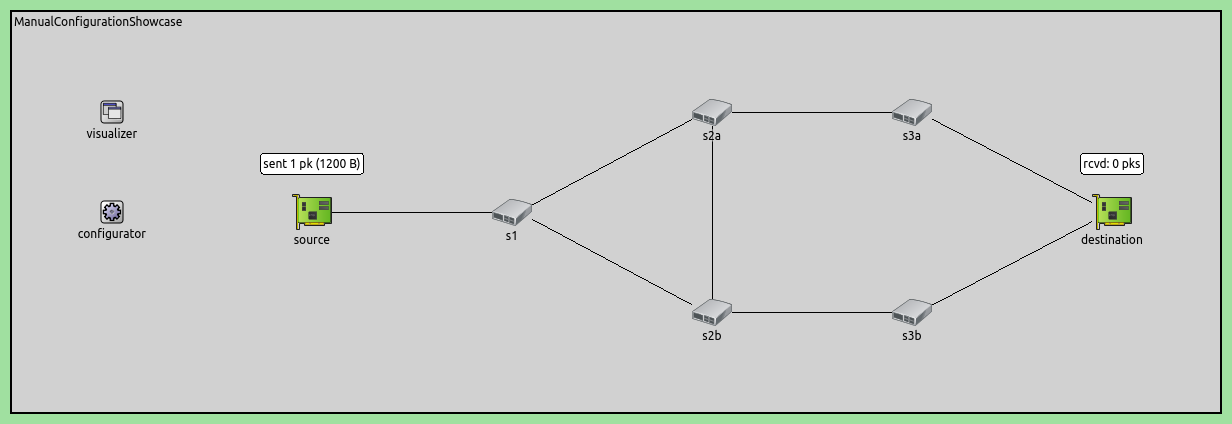
The network consists of:
source: Generates a UDP data stream
s1: First-level switch that performs the initial stream split
s2a, s2b: Second-level switches that provide cross-path redundancy
s3a, s3b: Third-level switches that forward streams to the destination
destination: Receives the stream and performs final duplicate elimination
Redundant Path Structure
The network topology provides four redundant paths from source to destination that are explicitly configured in this showcase:
Path 1 (Upper Direct): source → s1 → s2a → s3a → destination
Path 2 (Upper-to-Lower Zig-Zag): source → s1 → s2a → s2b → s3b → destination
Path 3 (Lower Direct): source → s1 → s2b → s3b → destination
Path 4 (Lower-to-Upper Zig-Zag): source → s1 → s2b → s2a → s3a → destination
The key to this redundancy is the connection between s2a and s2b, which creates the zig-zag paths (Paths 2 and 4). This mesh topology allows the network to tolerate multiple simultaneous link or node failures, as long as at least one complete path remains operational.
Failure Scenario
The configuration includes a controlled failure scenario to demonstrate the network’s resilience:
- At t=20ms: Switch s2a crashes
x Path 1 fails (uses s2a)
x Path 2 fails (uses s2a)
x Path 4 fails (uses s2a)
✓ Path 3 survives (source → s1 → s2b → s3b → destination)
- At t=80ms: Switch s2a recovers
✓ All four paths become operational again
During the failure period (20-80ms), Path 3 remains operational, ensuring continuous packet delivery. After recovery, the network returns to full redundancy with all four paths available.
This demonstrates that the mesh topology with FRER can maintain connectivity even during equipment failures, as long as at least one complete path remains operational.
The Model
In this showcase, we use the StreamRedundancyConfigurator with explicit path
specification through the trees parameter. This approach allows direct specification of
all redundant paths the network should use.
The configurator automatically:
Determines where streams must be replicated (split points)
Determines where duplicates must be eliminated (merge points)
Configures stream identification, encoding, and decoding at each node
Sets up MAC forwarding rules for the specified paths
The Configuration
The source generates UDP traffic at a constant rate:
*.source.numApps = 1
*.source.app[0].typename = "UdpSourceApp"
*.source.app[0].io.destAddress = "destination"
*.source.app[0].io.destPort = 1000
*.source.app[0].source.displayStringTextFormat = "sent %p pk (%l)"
*.source.app[0].source.packetLength = 1200B
*.source.app[0].source.productionInterval = 1ms
The source sends 1200-byte UDP packets every 1ms (100 packets during the 100ms simulation) to the destination node on port 1000.
The destination receives and counts the packets:
*.destination.numApps = 1
*.destination.app[0].typename = "UdpSinkApp"
*.destination.app[0].io.localPort = 1000
The ScenarioManager creates a deterministic node failure to test frame replication:
*.scenarioManager.script = xml("<script>\
                                  <at t='20ms'><crash module='s2a'/></at> \
                                  <at t='80ms'><startup module='s2a'/></at> \
                                </script>")
Switch s2a crashes at 20ms and recovers at 80ms, creating a 60ms outage window to demonstrate that frame replication maintains continuous packet delivery through the surviving path.
Configure all destination interfaces to share the same MAC address:
*.destination.eth[*].address = "0A-AA-12-34-56-78"
This setting is required so that frames arriving on any path (via eth[0] or eth[1]) can be accepted by the destination. Without this, frames would be rejected if they arrived on an interface not matching the destination MAC address.
Disable the automatic MAC forwarding table configurator:
*.macForwardingTableConfigurator.typename = ""
The automatic MAC forwarding table configurator must be disabled because frame replication uses IEEE 802.1CB custom forwarding rules (based on VLAN-tagged streams and explicit paths) rather than standard shortest path forwarding.
Configuring Redundant Paths
Enable IEEE 802.1CB frame replication and elimination functionality at all nodes:
*.*.hasStreamRedundancy = true
This activates stream identification, stream encoding/decoding, stream splitting (replication), and stream merging (duplicate elimination) capabilities in the bridging layer of all network nodes.
Configure the StreamRedundancyConfigurator to automatically set up frame replication and elimination:
*.streamRedundancyConfigurator.typename = "StreamRedundancyConfigurator"
The core of this showcase is the explicit path specification through the trees
parameter:
*.streamRedundancyConfigurator.configuration = [{name: "S1", packetFilter: "*", source: "source", destination: "destination",
                                                 trees: [[["source", "s1", "s2a", "s3a", "destination"]],
                                                         [["source", "s1", "s2b", "s3b", "destination"]],
                                                         [["source", "s1", "s2a", "s2b", "s3b", "destination"]],
                                                         [["source", "s1", "s2b", "s2a", "s3a", "destination"]]]}]
This configuration defines a stream named “S1” that applies to all packets from the
source application (using the wildcard packet filter “*”). The configuration explicitly
specifies the source and destination endpoints, and most importantly, lists four
redundant paths as node sequences in the trees parameter.
In general, the trees parameter accepts a list of multicast trees, where a tree
is given by a list of paths. In this example, we have a unicast stream, so each tree contains a single path.
Based on these four paths, the StreamRedundancyConfigurator automatically:
Determines split points: Identifies that frames must be replicated at:
s1: All four paths diverge here (initial 2-way split into upper/lower)
s2a: Paths 1 and 2 diverge (split between direct and zig-zag)
s2b: Paths 3 and 4 diverge (split between direct and zig-zag)
Determines merge points: Identifies where duplicates must be eliminated at:
s2a: Paths 1 and 4 converge (merge from direct and zig-zag)
s2b: Paths 2 and 3 converge (merge from direct and zig-zag)
destination: All paths converge (final elimination)
Configures forwarding: Sets up VLAN-based stream encoding/decoding and MAC forwarding rules at each switch to route frames along the specified paths
Assigns sequence numbers: Enables sequence numbering at the source for duplicate detection throughout the network
This explicit path specification approach gives complete control over the redundancy topology, which is useful when:
Specific paths are required for performance or policy reasons
The network topology is well-understood and optimized paths are known
You want to demonstrate or test specific redundancy configurations
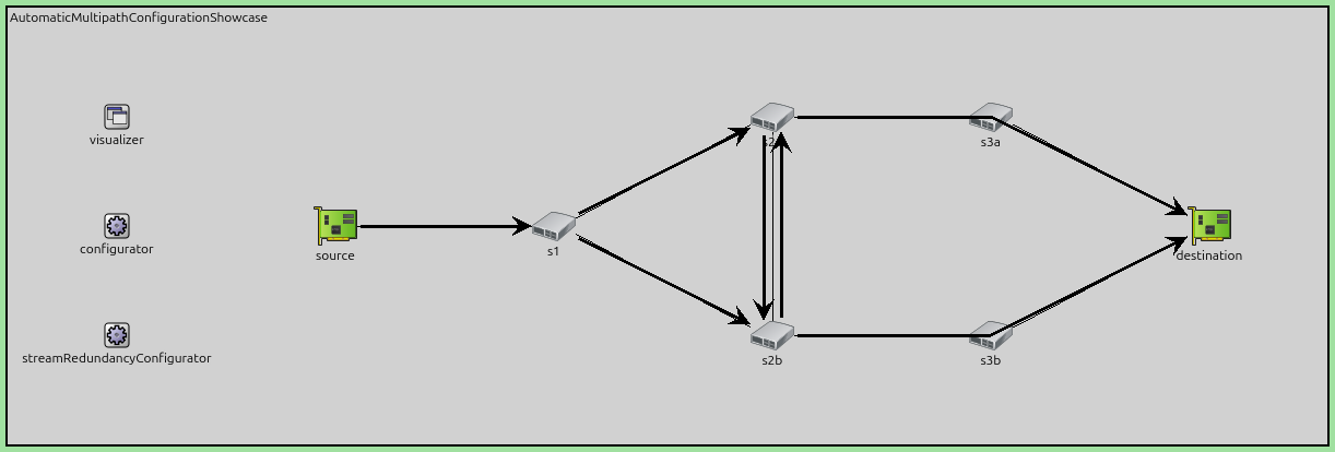
Results
The following image shows the output of the configurator, i.e. where streams are split and merged to create redundant paths:
The following video shows the streams in the network before and after the failure of s2a:
Despite the failure, Path 3 (the lower direct path) continues to operate, maintaining packet delivery throughout the failure period.
Here are the number of received and sent packets:
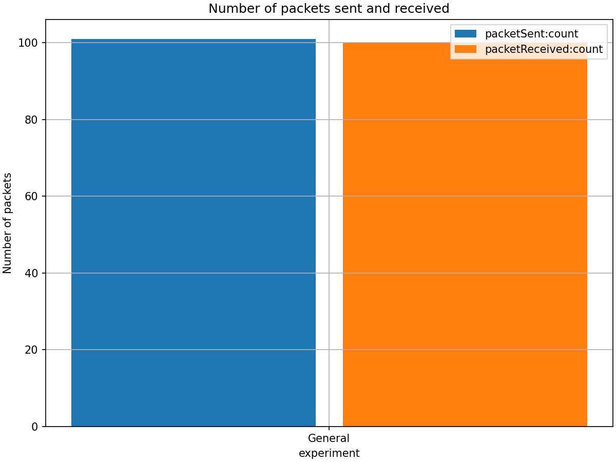
The number of sent packets is slightly more because some packets are still en-route in the network when the simulation ends.
The following chart shows the end-to-end delay:
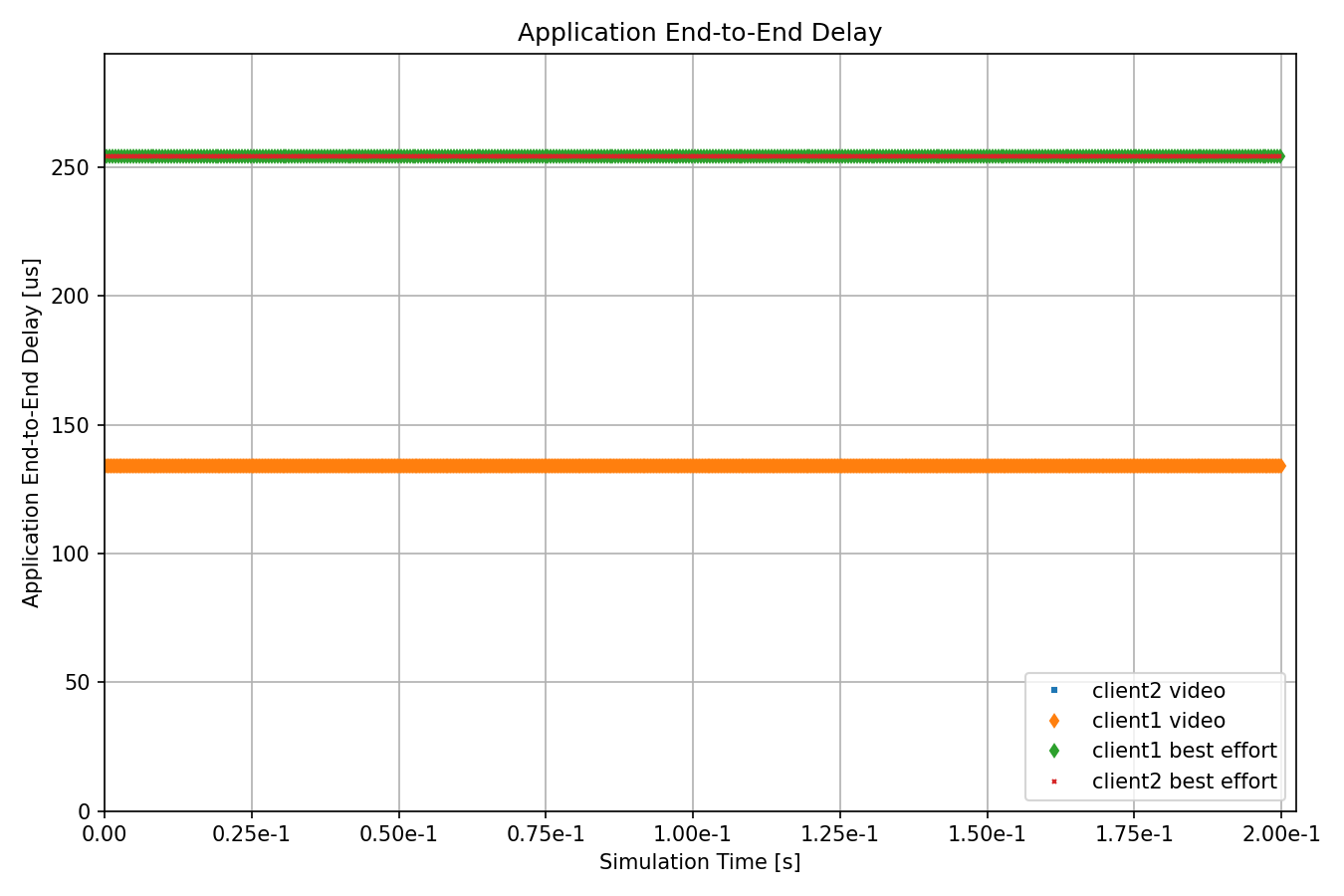
The delay chart demonstrates continuous packet delivery throughout the simulation. During normal operation (0-20ms and 80-100ms), packets are delivered via multiple paths. During the failure period (20-80ms), packets continue to be delivered exclusively via Path 3 without interruption, as evidenced by the absence of any gap in the delay measurements.
These results validate the effectiveness of the automatic FRER configuration with explicit path specification, demonstrating seamless failover and continuous packet delivery even during network equipment failures.
Note
For more details about what the configurator automates, see the Manual Stream Configuration showcase.
Sources: omnetpp.ini, AutomaticMultipathConfigurationShowcase.ned
Try It Yourself
If you already have INET and OMNeT++ installed, start the IDE by typing
omnetpp, import the INET project into the IDE, then navigate to the
inet/showcases/tsn/framereplication/automaticmultipathconfiguration folder in the Project Explorer. There, you can view
and edit the showcase files, run simulations, and analyze results.
Otherwise, there is an easy way to install INET and OMNeT++ using opp_env, and run the simulation interactively.
Ensure that opp_env is installed on your system, then execute:
$ opp_env run inet-4.6 --init -w inet-workspace --install --build-modes=release --chdir \
   -c 'cd inet-4.6.*/showcases/tsn/framereplication/automaticmultipathconfiguration && inet'
This command creates an inet-workspace directory, installs the appropriate
versions of INET and OMNeT++ within it, and launches the inet command in the
showcase directory for interactive simulation.
Alternatively, for a more hands-on experience, you can first set up the workspace and then open an interactive shell:
$ opp_env install --init -w inet-workspace --build-modes=release inet-4.6
$ cd inet-workspace
$ opp_env shell
Inside the shell, start the IDE by typing omnetpp, import the INET project,
then start exploring.
Discussion
Use this page in the GitHub issue tracker for commenting on this showcase.