Using gPTP
Goals
The Generic Precision Time Protocol (gPTP, as specified in IEEE 802.1AS) is a network protocol that can synchronize clocks with high accuracy. This is useful for applications such as Time-Sensitive Networking (TSN). In this showcase, we will demonstrate how to configure gPTP master clocks, bridges, and end stations to establish reliable time synchronization across the entire network.
4.6About gPTP
Overview
In reality, the time kept by clocks in different network devices can drift from each other. This clock drift can be simulated in INET (see the Clock Drift showcase for more information). In time-sensitive applications, this drift is mitigated by using time synchronization.
Having time synchronized between any two clocks means that the difference in time between them has an upper bound. This can be achieved by periodically synchronizing the time between the clocks (i.e., before the time difference gets too large). In gPTP, the times kept by a number of slave clocks are synchronized to a master clock’s time within a gPTP time domain. A network can have multiple gPTP time domains, i.e., nodes can synchronize multiple clocks to multiple master clocks for redundancy (in case one of the master clocks fails or goes offline due to link break, for example, nodes can still have synchronized time). Each time domain contains one master clock, and any number of slave clocks. The protocol synchronizes the slave clocks to the master clock by sending sync messages from the master clock nodes to the slave clock nodes.
According to the IEEE 802.1 AS standard, the master clock can be automatically selected by the Best Master Clock algorithm (BMCA). BMCA also determines the clock spanning tree, i.e., the routes on which sync messages are propagated to slave clocks in the network. INET currently doesn’t support BMCA; the master clock and the spanning tree needs to be specified manually for each gPTP time domain.
The operation of gPTP is summarized as follows:
All nodes compute the residence time (i.e., how much time a packet spends in a node before being forwarded) and up-tree link latency.
The gPTP sync messages are propagated down-tree.
Nodes calculate the precise time from the sync messages, the residence time and the latency of the link the sync message was received from.
gPTP in INET
In INET, the protocol is implemented by the Gptp application module. This
is an optional module in several network nodes, such as TSN hosts and switches.
The optional Gptp modules can be enabled with the
hasTimeSynchronization parameter in the ini file, for example:
*.tsnHost.hasTimeSynchronization = true
Nodes can be part of multiple gPTP time domains by having multiple Gptp submodules, one for each domain.
Gptp modules operate in one of three roles, according to their location in the spanning tree: master, bridge or slave.
Nodes containing master gPTP modules contain the master clock for the time
domain, create gPTP sync messages, and broadcast them down-tree to bridge and
slave nodes. Bridge nodes forward sync messages to bridge and slave nodes as
well. The module type can be selected by the Gptp module’s
gptpNodeType parameter (either MASTER_NODE, BRIDGE_NODE or
SLAVE_NODE)
Note
A network node might have different gPTP roles in different time domains, if there are several.
The spanning tree is created by labeling nodes’ interfaces (called ports) as
either a master or a slave, with the slavePort and masterPorts
parameters. Sync messages are sent on master ports, and received on slave ports.
Master nodes only have master ports, and slave nodes only slave ports (bridge
nodes have both). Consequently, since these ports define the spanning tree, each
node can have just one slave port.
The Gptp module has the following distinct mechanisms:
peer delay measurement: Slave and bridge nodes periodically measure link delay by sending peer delay request messages (
pDelayReq) up-tree; they receive peer delay response messages (pDelayResp).time synchronization: Master nodes periodically broadcast gPTP sync messages (
GptpSync) with their local time that propagate down-tree. The time of slave clocks is set to the time of the master clock, corrected for link and processing delays. Furthermore, the drift rate of slave clocks is aligned to that of the master clock by setting the oscillator compensation factor. The compensation factor is estimated from the time of the master and slave clocks at the current and the previous synchronization events.
Note
Recipients of these messages need to know the timestamp of when those messages were sent to be able to calculate “correct” time. Currently, only two-step synchronization is supported, i.e., pDelayResp and GptpSync messages are immediately proceeded by follow-up messages that contain the precise time when the original pDelayResp/GptpSync message was sent. Clocks are set to the new time when the follow-up message is received.
Nodes send sync and peer delay measurement messages periodically. The period and
offset of sync and peer delay measurement messages can be specified by
parameters (syncInterval, pDelayInterval,
syncInitialOffset, pDelayInitialOffset).
When nodes have multiple gPTP time domains, each time domain has a corresponding Gptp module. The MultiDomainGptp module makes this convenient, as it contains multiple Gptp modules. Also, each domain can have a corresponding clock module. The MultiClock module can be used for this purpose, as it contains multiple clock submodules.
One of the sub-clocks in the MultiClock module is designated as the active clock. Users of the MultiClock module (i.e., other modules that get the time from the MultiClock module) use the time of the active clock. The active clock can be changed by a scenario manager script to another sub-clock in case of failure of time synchronization in one domain, for example.
Note
When using MultiClock and MultiDomainGptp, it is enough to specify the MultiClock module to the MultiDomainGptp as the clock module. The corresponding sub-clock for each domain is selected automatically (i.e., Gptp submodules are paired to clock submodules in MultiClock based on index).
For more information on the parameters of Gptp, MultiDomainGptp, and MultiClock, check the NED documentation.
The Model
In this showcase, we demonstrate the setup and operation of gPTP in three simulations:
One Master Clock: Simple setup with one time domain and one master clock.
Primary and Hot-Standby Master Clocks: More complex setup with two time domains for a primary and a hot-standby master clock. If the primary master node goes offline, the stand-by clock can take over and become the new Master Clock.
Two Master Clocks Exploiting Network Redundancy: A larger network containing a primary and a hot-standby master node, with two time domains each. Time synchronization is protected against the failure of a master node and any link in the network.
In the General configuration, we enable Gptp modules in all network nodes, and configure a random clock drift rate for the master clocks, and a constant clock drift rate
for the clocks in slave and bridge nodes (specified with a random distribution for each one):
# enable time synchronization in all network nodes
*.*.hasTimeSynchronization = true

# all oscillators have a constant drift rate (specified with a random distribution for each one)
# except for the master clocks, which have a random drift rate
**.tsnClock*.clock.oscillator.typename = "RandomDriftOscillator"
**.oscillator.nominalTickLength = 10ns
**.oscillator.changeInterval = 12.5ms
**.oscillator.driftRate = uniform(-100ppm, 100ppm)
We detail each simulation in the following sections.
One Master Clock
In this configuration the network topology is a simple tree. The network contains one master clock node (TsnClock), one bridge and two end stations (TsnDevice), connected via a TsnSwitch:
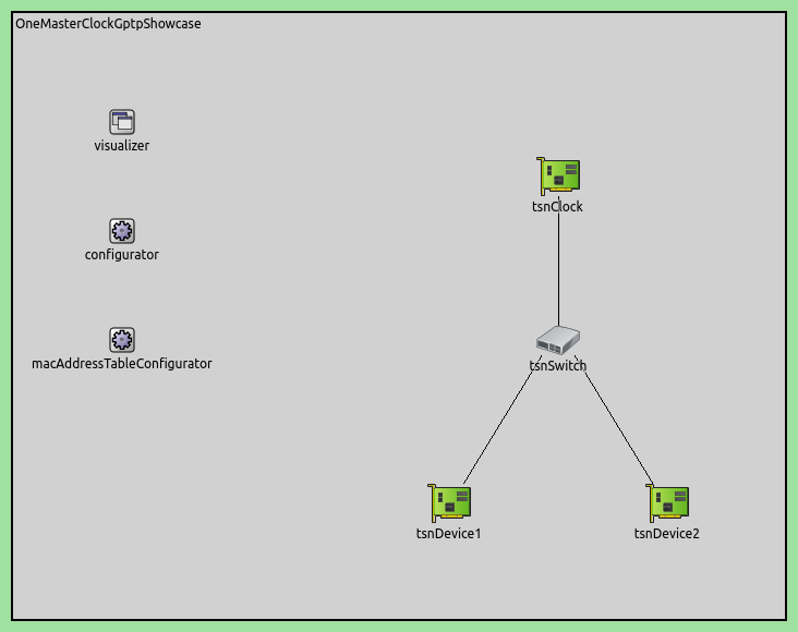
We configure the spanning tree by setting the master ports in tsnClock and tsnSwitch:
# TSN clock gPTP master ports
*.tsnClock.gptp.masterPorts = ["eth0"]

# TSN switch gPTP bridge master ports
*.tsnSwitch.gptp.masterPorts = ["eth1", "eth2"]
Note
The slave ports are set to eth0 by default in TsnDevice and TsnSwitch, so they don’t have to be set explicitly.
Here is a video of the synchronization mechanism (the time of the master clock and the difference from this time in the other nodes are displayed):
Note that the clocks are set after the follow up messages are received.
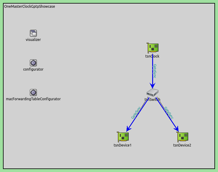
Here is the spanning tree indicated by the direction of gPTP sync messages:
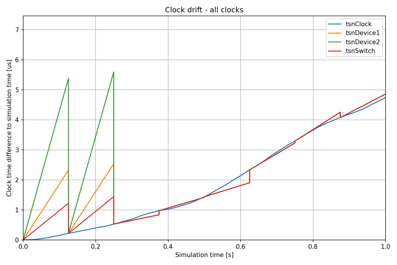
We examine clock drift of all clocks by plotting the clock time difference against simulation time:
Here is the same chart, but showing clock drift compared to the master clock:
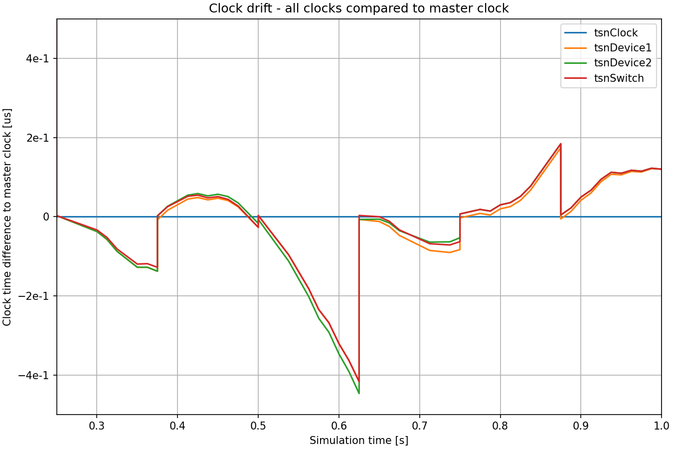
The master clock drifts according to a random walk process. The times of slave clocks is periodically synchronized to the master’s. At the second time synchronization event at 0.25s, the drift rates of the slave clocks are compensated to be more aligned with the master clock’s drift rate.
All such charts have these two large sawtooth patterns at the beginning, before the drift rate is compensated. From now on, we will generally omit these to concentrate on the details of the clock drift after it has been stabilized by time synchronization.
Note
A clock time difference to simulation time chart can be easily produced by plotting the timeChanged:vector statistic, and applying a linear trend operation with -1 as argument.
Primary and Hot-Standby Master Clocks
In this configuration the tree network topology is further extended. The network contains one primary master clock node and one hot-standby master clock node. Both master clock nodes have their own time synchronization domain. The switch and device nodes have two clocks, each synchronizing to one of the master clocks separately. The only connection between the two time domains is in the hot-standby master clock that is also synchronized to the primary master clock. This connection effectively causes the two time domains to be totally synchronized and allows seamless failover in the case of the master clock failure.
Note
This setup only contains the possibility of failover, but it isn’t actually demonstrated here. The master clock failure is demonstrated in the Effects of Time Synchronization on Time-Aware Shaping showcase.
The network contains two clock nodes (TsnClock) and four TSN device nodes (TsnDevice), connected by two TSN switches (TsnSwitch):
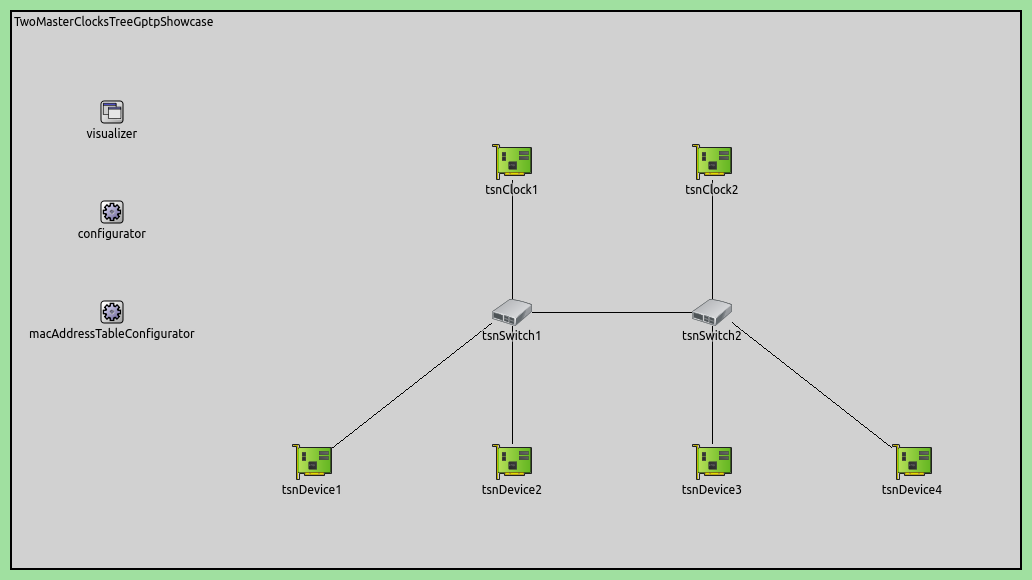
Our goal is to configure the two gPTP spanning trees for the two time domains. In this setup, the clock nodes have one clock, and the others have two (one for each domain).
tsnClock1(the primary master) has one clock and one gPTP domain, and disseminates timing information to domain 0 of all other nodes.tsnClock2(the hot-standby master) has one clock and two gPTP domains, and disseminates timing information of its domain 1 to domain 1 of all other nodes excepttsnClock1.The clock in
tsnClock2gets synchronized to the primary master node in domain 0.
Let’s see the configuration in omnetpp.ini, starting with settings for the clock nodes:
*.tsnClock2.clock.typename = "SettableClock"

*.tsnClock1.gptp.typename = "Gptp"
*.tsnClock1.gptp.clockModule = "tsnClock1.clock"
*.tsnClock1.gptp.masterPorts = ["eth0"]

*.tsnClock2.gptp.typename = "MultiDomainGptp"
*.tsnClock2.gptp.numDomains = 2
*.tsnClock2.gptp.domain[*].clockModule = "tsnClock2.clock"
*.tsnClock2.gptp.domain[0].gptpNodeType = "SLAVE_NODE"
*.tsnClock2.gptp.domain[0].slavePort = "eth0"
*.tsnClock2.gptp.domain[1].gptpNodeType = "MASTER_NODE"
*.tsnClock2.gptp.domain[1].masterPorts = ["eth0"]
We configure tsnClock2 to have a SettableClock, so we can set the
time. We configure tsnClock1 to have a Gptp module, and set it as a
master node. Also, we specify that it should use its own clock, and set the only
interface, eth0 to be a master port (the node will send gPTP sync messages
on that port).
In tsnClock2, we need two Gptp modules (one is a leaf, the other a
root in the tree), so we set the type of the gptp module to
MultiDomainGptp with two domains. Both domains use the only clock in the
node, but one of them acts as a gPTP master, the other one a gPTP slave (using
the same port, eth0).
Here is the configuration for the switches:
*.tsnSwitch*.clock.typename = "MultiClock"
*.tsnSwitch*.clock.numClocks = 2

# TSN switches have multiple gPTP time synchronization domains
*.tsnSwitch*.gptp.typename = "MultiDomainGptp"
*.tsnSwitch*.gptp.numDomains = 2
*.tsnSwitch1.gptp.domain[0].slavePort = "eth0"
*.tsnSwitch1.gptp.domain[0].masterPorts = ["eth1", "eth2", "eth3"]
*.tsnSwitch1.gptp.domain[1].slavePort = "eth1"
*.tsnSwitch1.gptp.domain[1].masterPorts = ["eth2", "eth3"]	# eth1 is omitted because no sync needed towards primary master
*.tsnSwitch2.gptp.domain[0].slavePort = "eth1"
*.tsnSwitch2.gptp.domain[0].masterPorts = ["eth0", "eth2", "eth3"]
*.tsnSwitch2.gptp.domain[1].slavePort = "eth0"
*.tsnSwitch2.gptp.domain[1].masterPorts = ["eth1", "eth2", "eth3"]
We configure the switches to have two clocks and two Gptp modules (one
for each domain). We then specify the spanning tree by setting the ports (the
gptpModuleType is BRIDGE_NODE by default in TsnSwitch, so we
don’t need to specify that). In both domains, the interface connecting to the
clock node is the slave port, and the others are master ports. The only
exception is that tsnSwitch1 shouldn’t send sync messages to tsnClock1
(as we don’t want it getting synchronized to anything), so the eth1
interface isn’t set as a master port.
Finally, here is the configuration for the devices:
*.tsnDevice*.clock.typename = "MultiClock"
*.tsnDevice*.clock.numClocks = 2

# TSN devices have multiple gPTP time synchronization domains
*.tsnDevice*.gptp.typename = "MultiDomainGptp"
*.tsnDevice*.gptp.numDomains = 2
*.tsnDevice1.gptp.clockModule = "tsnDevice1.clock"
*.tsnDevice2.gptp.clockModule = "tsnDevice2.clock"
*.tsnDevice3.gptp.clockModule = "tsnDevice3.clock"
*.tsnDevice4.gptp.clockModule = "tsnDevice4.clock"
*.tsnDevice*.gptp.domain[*].slavePort = "eth0"
Just as in the switches, we need two clocks and two Gptp modules in the
devices as well, so we use MultiClock and MultiDomainGptp with two
submodules. We configure each device’s gptp module to use the
MultiClock module in the device; the appropriate sub-clock for the domain
is automatically selected. We set all gptp modules to use the only interface
as the slave port (the Gptp module type is SLAVE_NODE by default in
TsnDevice, so we don’t need to configure that).
We also configure some offsets for the pDelay measurement and gPTP sync messages in the different domains so they are not transmitted concurrently and suffer queueing delays.
**.pdelayInitialOffset = 100us
*.*.gptp.domain[0].syncInitialOffset = syncInterval * 1 / 2
*.*.gptp.domain[1].syncInitialOffset = syncInterval * 2 / 2
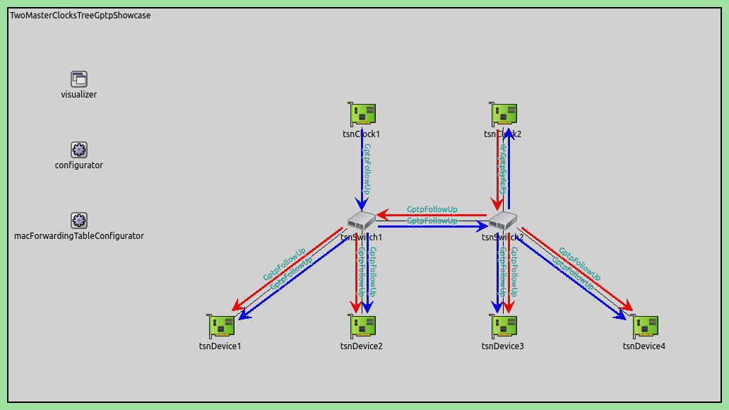
The following is a video of the time synchronization process at the beginning of the simulation. The clock time in master nodes, and the time difference to this clock time in the other nodes are displayed for each clock. Messages for gPTP are visualized as arrows. The visualization is color-coded according to domain:
First, the bridge and slave nodes measure link delay by exchanging pDelay messages. Then, the master clocks send gPTP sync messages. Note that there is a jump in the time difference when the clocks are set to the new time after the gPTP follow-up messages are received.
This setup is protected against the failure of the master clock. In that case, a
scenario manager script could switch the nodes in the network to gPTP domain 1,
i.e., the active clock in MultiClock could be switched to the
clock[1] submodule, without affecting time synchronization.
The spanning tree is visualized as the datalink-layer gPTP message transmissions. This outlines the flow of timing information in the network, originating from the master clock:
Let’s examine some clock drift charts. Instead of plotting clock drift for all clocks in one chart, let’s use three charts so they are less cluttered. Here is the clock drift (clock time difference to simulation time) of the two master clocks:
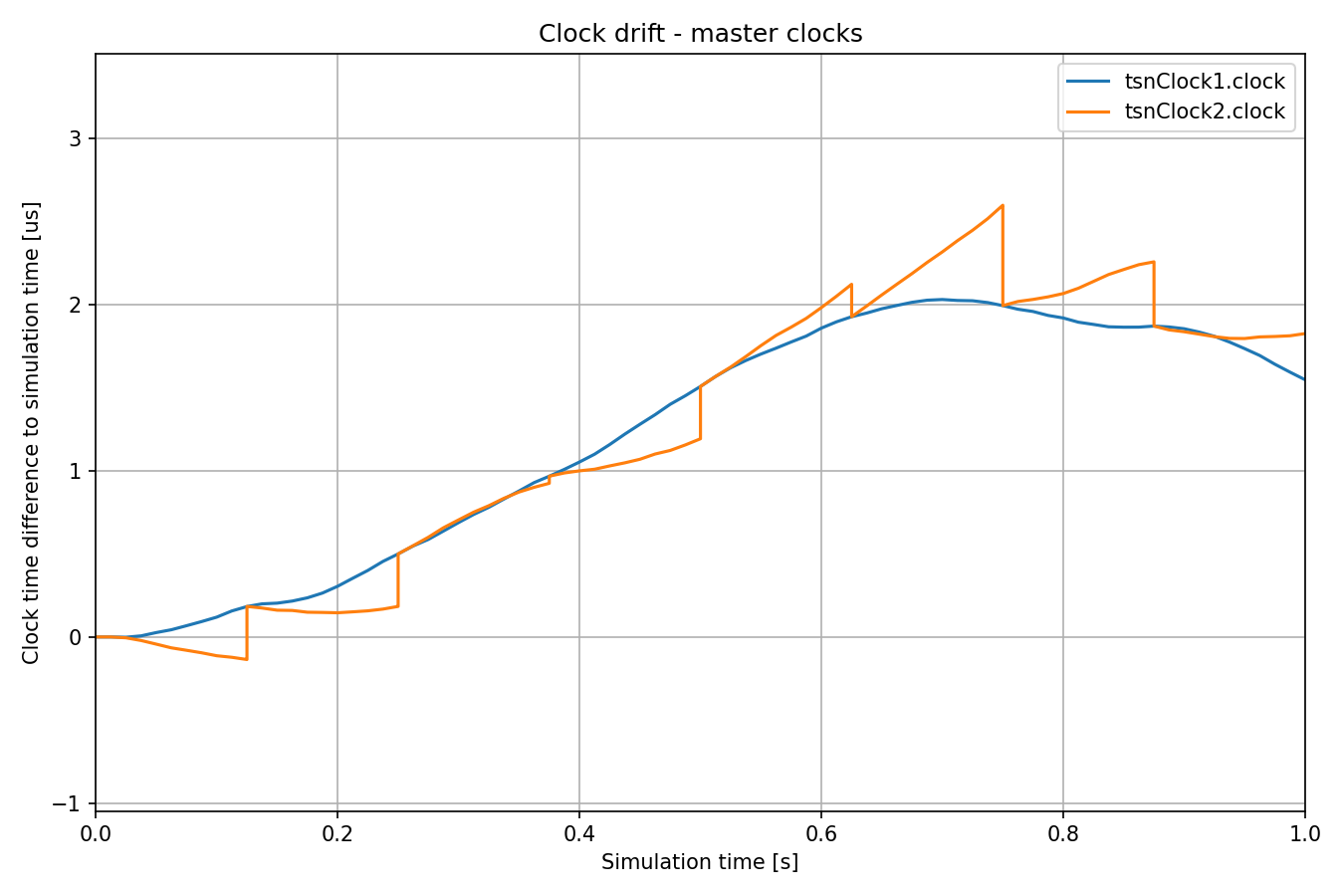
Both master clocks have a random drift rate, but the hot-standby master clock’s time and clock drift rate are periodically synchronized to the primary.
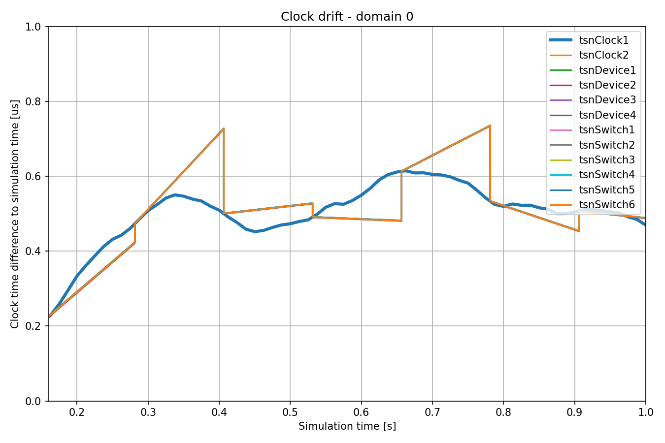
Here is the clock drift of all clocks in time domain 0 (primary master):
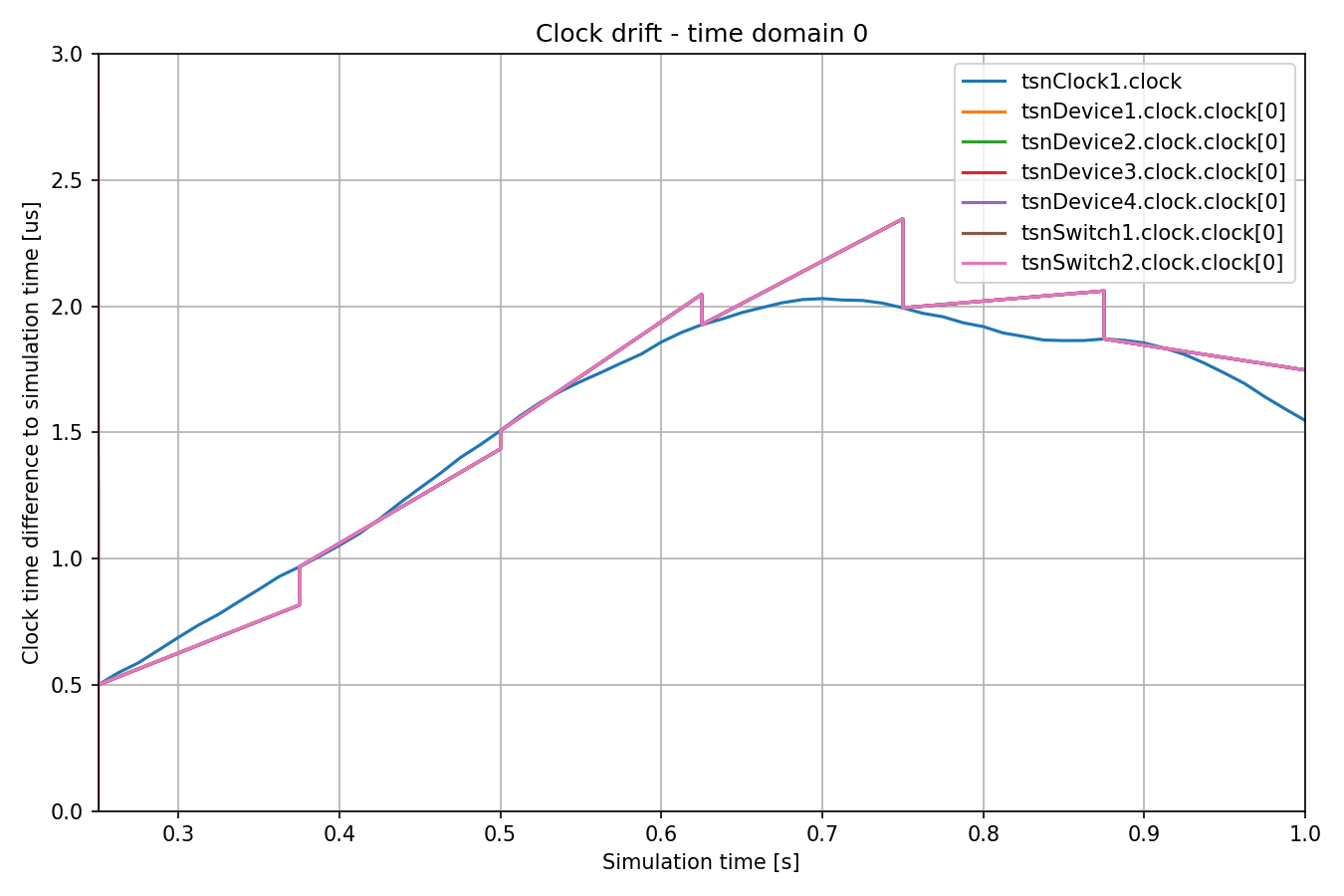
Each slave clock has a distinct but constant drift rate, while the master clock’s drift rate fluctuates randomly. The slave clocks are periodically synchronized with the master clock. After the initial two synchronization events (not displayed on the chart), the drift rate of the slave clocks is adjusted to align with that of the master clock. However, the oscillator compensation factor in each slave clock is determined by the drift rate at the current and previous synchronization points. But since the master clock’s drift rate continues to change, the slave clocks can still drift away from the master clock. It is worth noting that after the first rate compensation, all the slave clocks have almost equal compensated drift rate. The differences are due to the inherently inaccurate synchronization process.
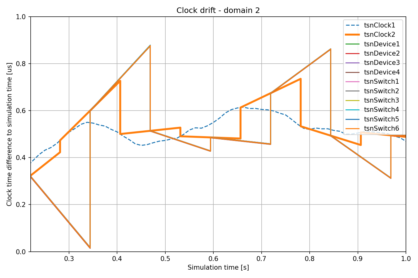
Let’s see the clock drift for all clocks in time domain 1 (hot-standby master):
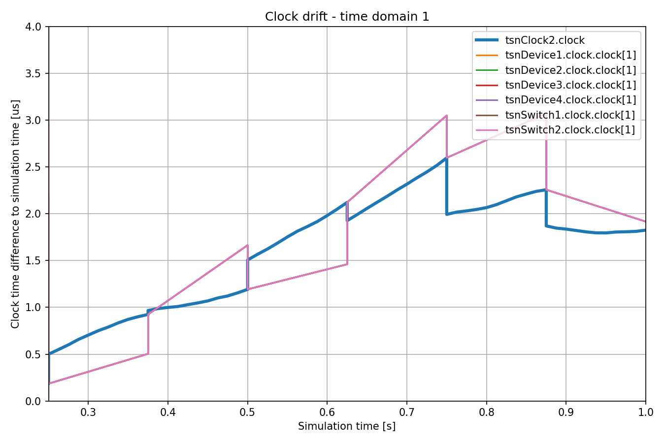
The clocks have different drift rates, and they are periodically synchronized to the hot-standby master clock (displayed with the thick blue line). The hot-standby master clock itself drifts from the primary master, and gets synchronized periodically. The upper bound of the time difference is apparent on the chart.
Note that the slave clocks in domain 1 get synchronized just before the time of the hot stand-by master clock is updated in domain 0. As in the previous cases, the drift rate of slave clocks is compensated to be more aligned with the master clock’s rate.
Note
The magnitude of slave clock divergence from the master clock might appear to be large on these charts, but it is only in the order of microseconds (the scale of the y axis is a millionth of the x axis).
In the next section, we make the network more redundant, so that the primary master clock and any link in the network can fail without breaking time synchronization.
Two Master Clocks Exploiting Network Redundancy
In this configuration the network topology is a ring. The primary master clock and the hot-standby master clock each have two separate time domains. One time domain uses the clockwise and another one uses the counterclockwise direction in the ring topology to disseminate the clock time in the network. This approach provides protection against the failure of the primary master node and a single link failure in the ring because all bridges can be reached in both directions by one of the time synchronization domains of both master clocks.
Here is the network (it uses the same node types as the previous ones, TsnClock, TsnSwitch and TsnDevice):
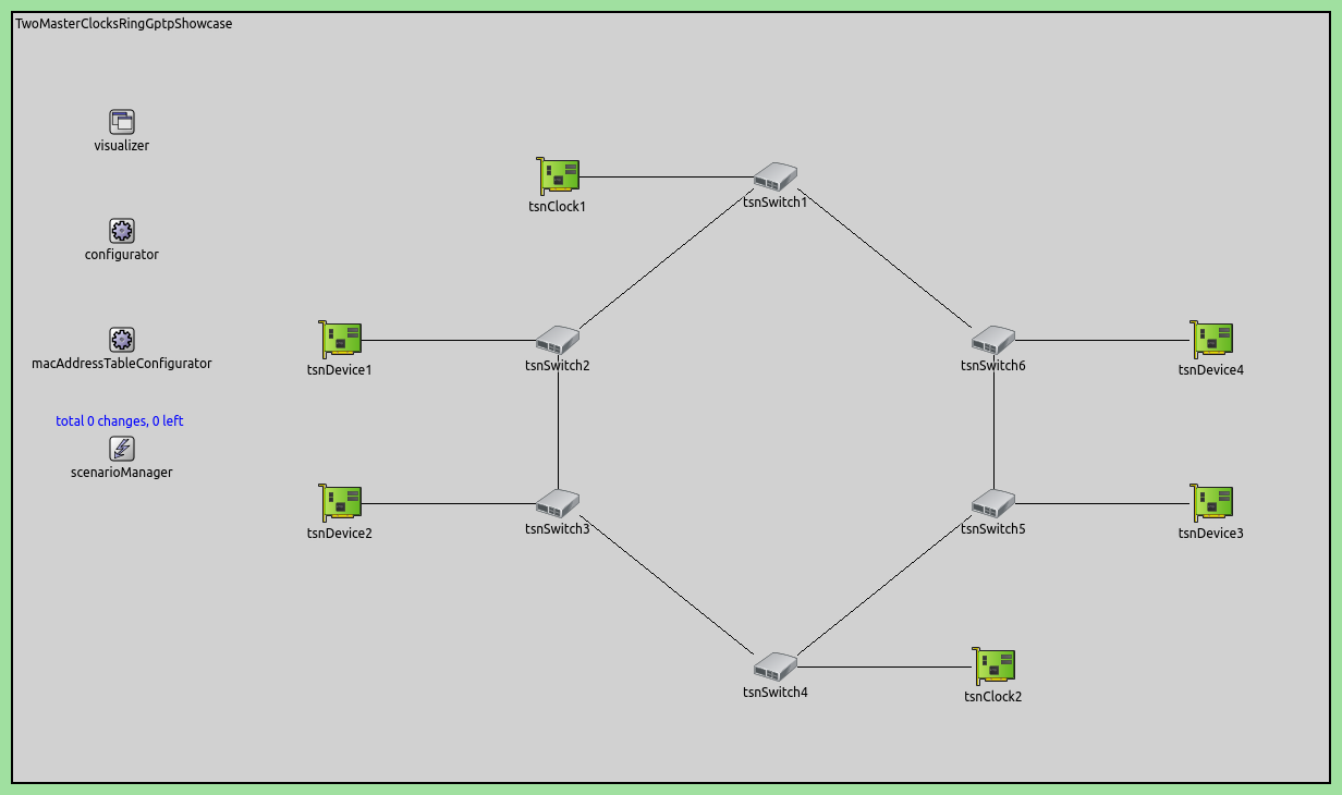
The time synchronization redundancy is achieved in the following way:
The primary master node has one clock and two master gPTP time domains. The domains send timing information in the ring in the clockwise and counterclockwise direction.
The hot-standby master node has two slave and two master gPTP domains, and two sub-clocks. Domains 0 and 1 sync the two clocks to the primary master’s two domains, and domains 2 and 3 send timing information of the two clocks in both directions in the ring.
Switch and device nodes have four domains (and four sub-clocks), with domains 0 and 1 syncing to the primary master node, and domains 2 and 3 to the hot-standby master node.
Consequently, gPTP modules in the switches are gPTP bridges, in the devices, gPTP slaves.
In case of failure of the primary master node and a link in the ring, the switches and devices would have at least one synchronized clock they could switch over to.
How do we configure this scheme? We add the needed gPTP domains and clocks, and configure the spanning tree outlined above. Some important aspects when setting the ports and clocks:
We don’t want to forward any timing information to the primary master node, so we set the master ports in
tsnSwitch1accordingly.We take care not to forward timing messages to a switch that originally sent it (so sync messages don’t go in circles indefinitely). For example, tsnSwitch6 shouldn’t send sync messages to
tsnSwitch1in domain 0.The hot-standby master node has just two clocks, used by the four domains. The timing information from domains 0 and 1 is transferred to domains 2 and 3 here. So we set domains 0 and 2 to use
clock[0], and domains 1 and 3 to useclock[1].
Here is the configuration for the clock nodes:
[Config TwoMasterClocksExploitingNetworkRedundancy]
network = TwoMasterClocksRingGptpShowcase
description = "Ring topology with redundant time synchronization domains"
# clock visualization note: bridge and slave nodes display difference from corresponding master clock

# TSN clock2 has multiple clocks
*.tsnClock2.clock.typename = "MultiClock"
*.tsnClock2.clock.numClocks = 2

# TSN clocks have multiple gPTP time synchronization domains
*.tsnClock*.gptp.typename = "MultiDomainGptp"
*.tsnClock1.gptp.numDomains = 2
*.tsnClock1.gptp.domain[0..1].clockModule = "tsnClock1.clock"
*.tsnClock1.gptp.domain[0].masterPorts = ["eth0"]
*.tsnClock1.gptp.domain[1].masterPorts = ["eth0"]
*.tsnClock2.gptp.numDomains = 4
*.tsnClock2.gptp.domain[2..3].clockModule = "tsnClock2.clock"
*.tsnClock2.gptp.domain[0].gptpNodeType = "SLAVE_NODE"
*.tsnClock2.gptp.domain[0].slavePort = "eth0"
*.tsnClock2.gptp.domain[1].gptpNodeType = "SLAVE_NODE"
*.tsnClock2.gptp.domain[1].slavePort = "eth0"
*.tsnClock2.gptp.domain[2].gptpNodeType = "MASTER_NODE"
*.tsnClock2.gptp.domain[2].masterPorts = ["eth0"]
*.tsnClock2.gptp.domain[3].gptpNodeType = "MASTER_NODE"
*.tsnClock2.gptp.domain[3].masterPorts = ["eth0"]
We set tsnClock1 to have two Gptp modules, each using the only clock
in the host. The type of the clock network nodes is TsnClock; in these,
the Gptp modules are set to master by default. We set the master ports in
both modules, so they disseminate timing information on their only Ethernet
interface.
tsnClock2 is set to have four gPTP domains. Since tsnClock2 has only two
sub-clocks, we need to specify that domains 2 and 3 use clock[0] and
clock[1] in the MultiClock module (it is sufficient to set the
clockModule parameter to the MultiClock module, as it assigns the
sub-clocks to the domains automatically).
Thus, in tsnClock2, domains 0 and 1 are gPTP slaves, syncing to the two
domains of the primary master. Domains 2 and 3 are gPTP masters, and disseminate
the time of the clocks set by the first two domains.
The configuration for the switches is the following:
# TSN switches have multiple clocks
*.tsnSwitch*.clock.typename = "MultiClock"
*.tsnSwitch*.clock.numClocks = 4

# TSN switches have multiple gPTP time synchronization domains
*.tsnSwitch*.gptp.typename = "MultiDomainGptp"
*.tsnSwitch*.gptp.numDomains = 4

# TSN switch 1
*.tsnSwitch1.gptp.domain[0].masterPorts = ["eth1"]
*.tsnSwitch1.gptp.domain[0].slavePort = "eth0"
*.tsnSwitch1.gptp.domain[1].masterPorts = ["eth2"]
*.tsnSwitch1.gptp.domain[1].slavePort = "eth0"
*.tsnSwitch1.gptp.domain[2].masterPorts = ["eth1"]
*.tsnSwitch1.gptp.domain[2].slavePort = "eth2"
*.tsnSwitch1.gptp.domain[3].masterPorts = ["eth2"]
*.tsnSwitch1.gptp.domain[3].slavePort = "eth1"

# TSN switch 2
*.tsnSwitch2.gptp.domain[0].masterPorts = ["eth1", "eth2"]
*.tsnSwitch2.gptp.domain[0].slavePort = "eth0"
*.tsnSwitch2.gptp.domain[1].masterPorts = ["eth2"]
*.tsnSwitch2.gptp.domain[1].slavePort = "eth1"
*.tsnSwitch2.gptp.domain[2].masterPorts = ["eth1", "eth2"]
*.tsnSwitch2.gptp.domain[2].slavePort = "eth0"
*.tsnSwitch2.gptp.domain[3].masterPorts = ["eth0", "eth2"]
*.tsnSwitch2.gptp.domain[3].slavePort = "eth1"

# TSN switch 3
*.tsnSwitch3.gptp.domain[0].masterPorts = ["eth1", "eth2"]
*.tsnSwitch3.gptp.domain[0].slavePort = "eth0"
*.tsnSwitch3.gptp.domain[1].masterPorts = ["eth0", "eth2"]
*.tsnSwitch3.gptp.domain[1].slavePort = "eth1"
*.tsnSwitch3.gptp.domain[2].masterPorts = ["eth2"]
*.tsnSwitch3.gptp.domain[2].slavePort = "eth0"
*.tsnSwitch3.gptp.domain[3].masterPorts = ["eth0", "eth2"]
*.tsnSwitch3.gptp.domain[3].slavePort = "eth1"

# TSN switch 4
*.tsnSwitch4.gptp.domain[0].masterPorts = ["eth0", "eth2"]
*.tsnSwitch4.gptp.domain[0].slavePort = "eth1"
*.tsnSwitch4.gptp.domain[1].masterPorts = ["eth0", "eth1"]
*.tsnSwitch4.gptp.domain[1].slavePort = "eth2"
*.tsnSwitch4.gptp.domain[2].masterPorts = ["eth2"]
*.tsnSwitch4.gptp.domain[2].slavePort = "eth0"
*.tsnSwitch4.gptp.domain[3].masterPorts = ["eth1"]
*.tsnSwitch4.gptp.domain[3].slavePort = "eth0"

# TSN switch 5
*.tsnSwitch5.gptp.domain[0].masterPorts = ["eth1", "eth2"]
*.tsnSwitch5.gptp.domain[0].slavePort = "eth0"
*.tsnSwitch5.gptp.domain[1].masterPorts = ["eth0", "eth2"]
*.tsnSwitch5.gptp.domain[1].slavePort = "eth1"
*.tsnSwitch5.gptp.domain[2].masterPorts = ["eth1", "eth2"]
*.tsnSwitch5.gptp.domain[2].slavePort = "eth0"
*.tsnSwitch5.gptp.domain[3].masterPorts = ["eth2"]
*.tsnSwitch5.gptp.domain[3].slavePort = "eth1"

# TSN switch 6
*.tsnSwitch6.gptp.domain[0].masterPorts = ["eth2"]
*.tsnSwitch6.gptp.domain[0].slavePort = "eth0"
*.tsnSwitch6.gptp.domain[1].masterPorts = ["eth0", "eth2"]
*.tsnSwitch6.gptp.domain[1].slavePort = "eth1"
*.tsnSwitch6.gptp.domain[2].masterPorts = ["eth1", "eth2"]
*.tsnSwitch6.gptp.domain[2].slavePort = "eth0"
*.tsnSwitch6.gptp.domain[3].masterPorts = ["eth0", "eth2"]
*.tsnSwitch6.gptp.domain[3].slavePort = "eth1"
Here is the configuration for the devices:
*.tsnDevice*.clock.typename = "MultiClock"
*.tsnDevice*.clock.numClocks = 2

# TSN devices have multiple gPTP time synchronization domains
*.tsnDevice*.gptp.typename = "MultiDomainGptp"
*.tsnDevice*.gptp.numDomains = 2
*.tsnDevice1.gptp.clockModule = "tsnDevice1.clock"
*.tsnDevice2.gptp.clockModule = "tsnDevice2.clock"
*.tsnDevice3.gptp.clockModule = "tsnDevice3.clock"
*.tsnDevice4.gptp.clockModule = "tsnDevice4.clock"
*.tsnDevice*.gptp.domain[*].slavePort = "eth0"
Finally, we configure offsets for the four domains, so that they don’t send sync messages at the same time:
**.pdelayInitialOffset = 0.1ms
*.*.gptp.domain[0].syncInitialOffset = syncInterval * 1 / 4
*.*.gptp.domain[1].syncInitialOffset = syncInterval * 2 / 4
*.*.gptp.domain[2].syncInitialOffset = syncInterval * 3 / 4
*.*.gptp.domain[3].syncInitialOffset = syncInterval * 4 / 4
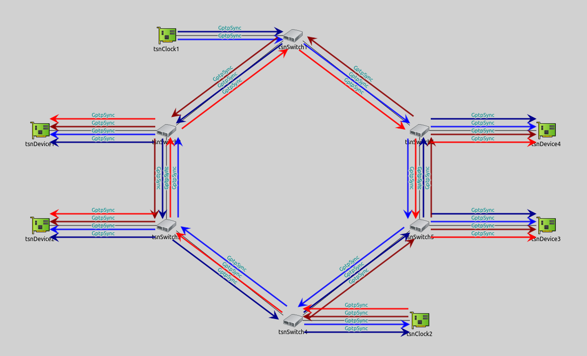
Here is the spanning tree visualized by gPTP messages:
Just as in the previous sections, let’s examine the clock drift of the different clocks in the network. Here is the clock drift of the master clocks:
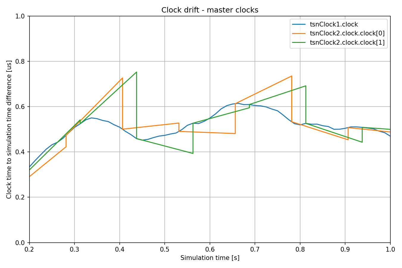
The clocks of the hot-standby master node are synced to the time of the primary master periodically. Note that the sync times have the offset we configured. Let’s see the clock drifts in domain 0 (the primary master clock is plotted with the thicker line):
In Domain 0, all clocks sync to the primary master clock. They sync at the same time, because the offsets are between domains. The clock drift in Domain 1 is similar, so we don’t include it here. Let’s see Domain 2 (the primary master clock is displayed with a dashed line for reference, as it’s not part of this domain; the hot-standby master clock in this domain is displayed with the thicker line):
All switches and devices sync to the hot-standby master clock (which itself is synced to the primary master periodically).
Note
The charts for all domains are available in the .anf file in the showcase’s folder.
Sources: omnetpp.ini, GptpShowcase.ned
Try It Yourself
If you already have INET and OMNeT++ installed, start the IDE by typing
omnetpp, import the INET project into the IDE, then navigate to the
inet/showcases/tsn/timesynchronization/gptp folder in the Project Explorer. There, you can view
and edit the showcase files, run simulations, and analyze results.
Otherwise, there is an easy way to install INET and OMNeT++ using opp_env, and run the simulation interactively.
Ensure that opp_env is installed on your system, then execute:
$ opp_env run inet-4.6 --init -w inet-workspace --install --build-modes=release --chdir \
   -c 'cd inet-4.6.*/showcases/tsn/timesynchronization/gptp && inet'
This command creates an inet-workspace directory, installs the appropriate
versions of INET and OMNeT++ within it, and launches the inet command in the
showcase directory for interactive simulation.
Alternatively, for a more hands-on experience, you can first set up the workspace and then open an interactive shell:
$ opp_env install --init -w inet-workspace --build-modes=release inet-4.6
$ cd inet-workspace
$ opp_env shell
Inside the shell, start the IDE by typing omnetpp, import the INET project,
then start exploring.
Discussion
Use this page in the GitHub issue tracker for commenting on this showcase.