Measuring Time Along Packet Flows
Goals
This showcase demonstrates how to group packets into flows for the purpose of taking measurements on them, such as elapsed time, time spent in queues, or transmission time.
4.6The Model
The following sections contain an overview of measuring time associated with packets. For more information, refer to the Collecting Results section of the INET manual.
Overview of Packet Flows
By default, statistics in INET are collected based on local events associated with a particular module (e.g. packets received by the module). Sometimes this local data might not be sufficient. For example, when we want to measure the incurred queueing time separately for packets that arrived at the same destination but took different paths in the network.
For timing measurements that are associated with events happening to a packet, packet flows can be defined. A packet flow is a logical classification of packets, identified by its name, in the whole network and over the whole duration of the simulation. A packet flow is defined by a label that is added to some packets. The label contains the flow name (the flow’s identity), and some specified measurement requests.
Time measurement along packet flows is useful in situations when the timing data to be measured is associated with a packet, rather than the modules it passes through, gets processed by, or arrives at. For example, we might want to measure the queueing time for a packet at all the modules it passes through, as opposed to measuring queueing time at a queue module for all packets that it processes.
A packet is associated with the flow by specialized modules called measurement starters. These modules attach a label to the packet that indicates which flow it is part of and what measurements are requested. When the packet travels through the network, certain modules add the measured time (or other data) to the packet as meta-information. Other specialized modules (measurement recorders) record the attached data as a statistic associated with that particular flow. These modules can optionally remove the label from the packet (then the packet can continue along its route).
For example, a label is added to the packet in a measurement starter module
specifying the flow name flow1 and the queueing time measurement. As the
packet is processed in various queue modules in the network, the queue modules
attach the time spent in them to the packet as meta-information. The label is
removed at a measurement recorder module, and the queueing time accumulated by
the packet is recorded. The data can be found in the analysis tool’s browse data
tab as the flowname:statisticname result name of the measurement recorder
module (for example, flow1:queueingTime:histogram). By default,
FlowMeasurementRecorder records the specified measurements as both
vectors and histograms. The statistics can be plotted, exported, and analyzed as
any other statistic.
Any number of flow labels can be added to a packet (it can be part of multiple flows). Also, the same flow can have multiple start and end points.
Note
A practical problem is that different parts of a packet may have different history, due to fragmentation and reassembly, for example. Therefore, we need to keep track of the measurements for different regions of the packet. For this purpose, each bit in a packet can have its own meta-information associating it with a flow, called a region tag. For more information on region tags, check out the Region Tagging section of the INET Developer’s Guide.
The Measurement Modules
The dedicated module responsible for adding flow labels and specifying measurements to be made on packets is the FlowMeasurementStarter. Its counterpart responsible for removing flow labels and recording measurements is the FlowMeasurementRecorder module.
The FlowMeasurementStarter and FlowMeasurementRecorder modules
have the same set of parameters that specify the flow name (flowName
parameter), the set of packets that enter or exit the flow (packetFilter
parameter), and the required measurements (measure parameter).
By default, the filters match all packets (packetFilter = '*'). The
measure parameter is a list containing elements from the following set,
separated by spaces:
delayingTime,queueingTime,processingTime,transmissionTime,propagationTime: Time for the different cases, on a per-bit basiselapsedTime: The total elapsed time for the packet being in the flow (see first note below)packetEvent: Record all events that happen to the packet (see second note below)
The FlowMeasurementRecorder module removes flow labels from packets by
default. This is controlled by the endMeasurement parameter (true by
default).
Some notes:
Evaluating the measured data when there is cut-through switching or intra-node packet streaming in the network can be more complex than if there is not. This is because measurements are recorded on a per-bit basis, and the transmission time can be different for each bit if there is packet streaming in the network. Also, bits waiting in the transmitter for other bits of a packet to be transmitted and received is only included in the elapsed time measurement. Because of this, the sum of all other measurements might not be equal to the elapsed time.
The
packetEventmeasurement is special, because it records the history of the packet as it travels through the network, instead of taking a specific measurement. For example, it records events of the packet’s delaying, queueing, processing, transmission, etc. There is no built-in module that makes use of the packet event measurement data, this can be implemented by the user. This can be useful for more detailed analysis based on a packet’s history.Although both the measurement starter and recorder modules have a
measureparameter, its meaning is slightly different. For the measurement starter module, the parameter specifies which measurement data to include in the attached flow tag. For the measurement recorder module, it specifies which measurements to record as statistics. Generally, the parameter values for the recorder module should be the same or a subset of the starter module’s parameters. If a recorder module is configured to record a measurement that isn’t on the packet (not set to record in the starter module), the measurement silently fails. Thus it is the user’s responsibility to set up themeasureparameters properly.
Adding Measurement Modules to the Network
The FlowMeasurementStarter and FlowMeasurementRecorder modules can be inserted
anywhere in the network (inside network nodes or protocol modules, etc.) in NED
by editing the NED source of modules or extending them as a new type. However,
some modules such as the LayeredEthernetInterface already have built-in
MeasurementLayer submodules. This module contains a
FlowMeasurementStarter and a FlowMeasurementRecorder, but they are disabled by
default (the type is set to empty string). The modules can be enabled from the
.INI file (e.g. *.host.eth[0].measurementLayer.typename =
"MeasurementLayer"):
Associating Packets to Flows Based on Multiple Criteria
A measurement module can filter which packets to associate with a flow, using a
packet filter and a packet data filter. Packets can be associated with multiple
flows based on multiple criteria by using several measurement modules connected
in series. The MultiMeasurementLayer module makes this convenient. It can be
used in place of a MeasurementLayer module. It contains a variable number of
FlowMeasurementStarter and FlowMeasurementRecorder modules; the number of
modules is specified with its numMeasurementModules parameter. For
example, numMeasurementModules = 2:
The example simulations demonstrate both inserting measurement modules into specific locations (below the Udp module) and using built-in MeasurementLayer submodules.
Visualizing Packet Flows
The module type PacketFlowVisualizer (also included in
IntegratedCanvasVisualizer) can display packet flows in the network as dashed
arrows annotated by the flow name. The arrows are color-coded so that flows can
be differentiated by color. The visualization can be enabled with the
displayRoutes parameter, e.g.
*.visualizer.packetFlowVisualizer.displayRoutes = true in the .INI
file.
Example Simulations
This showcase contains two simulations. Both simulations use the following network:
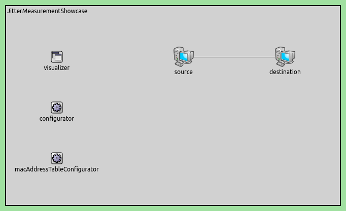
The network contains hosts connected via switches (EthernetSwitch) in a dumbbell topology. Note that the host types are parametric (so that they can be configured from the INI file):
client1: <default("StandardHost")> like IEthernetNetworkNode {
Example 1: Enabling Measurement Modules
This simulation demonstrates grouping packets into packet flows and measuring time along the flows, using measurement modules built into UDP apps and Ethernet interfaces.
Configuration
The host type is StandardHost. Two UDP apps in both clients send packets
to the servers (app[0] to server1, app[1] to server2); each
server has a UDP app that accepts the packets. This traffic results in four
streams of packets. Let’s denote server with s, and client with
c. The four streams, using origin-destination pairs to refer to them, are
c1s1, c1s2, c2s1, c2s2.
We want to measure the following:
Elapsed time and queueing time for traffic between the originating and destination UDP apps, individually for the four client-server packet streams.
Elapsed time and queueing time for all traffic between the two Ethernet interfaces connecting the switches.
For this purpose, we specify five packet flows, and measure elapsed time and queueing time along the following flows:
Four packet flows corresponding to the packet streams
c1s1,c1s2,c2s1andc2s2(i.e. each flow is between the client and server UDP apps)A packet flow going between the Ethernet interfaces connecting
switch1andswitch2.
For simplicity, let’s name the packet flows according to the
origin-destination naming scheme mentioned above (let’s abreviate switch as
sw). Thus, we have the following packet flows: c1s1, c1s2, c2s1,
c2s2 and sw1sw2
The following is a screenshot showing the five defined packet flows in action:
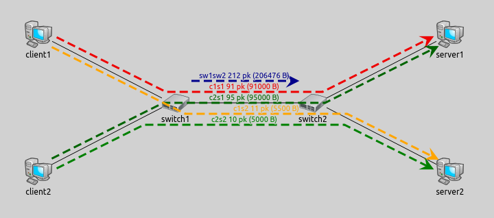
Note
A packet can be part of several flows to enable different measurements. For example in the image above, each of the four flows originating from the clients are also part of the flow between the two switches.
Let’s see how we set up these flows. The UDP apps in the clients and servers are
the UdpSourceApp and UdpSinkApp type, which are versions of the
modular UdpApp suitable only to work as a packet source or sink,
respectively. These modules have optional measurementStarter and
measurementRecorder submodules that we can enable in the .INI file. We
enable the measurement starter (by setting its type to
FlowMeasurementStarter) in the clients:
*.client*.app[*].measurementStarter.typename = "FlowMeasurementStarter"
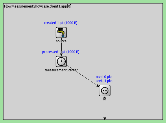
Here is the FlowMeasurementStarter in a client’s UDP app:
Similarly, we enable the measurement recorder module in the server UDP apps (by setting their type to FlowMeasurementRecorder):
*.server*.app[*].measurementRecorder.typename = "FlowMeasurementRecorder"
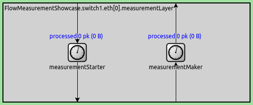
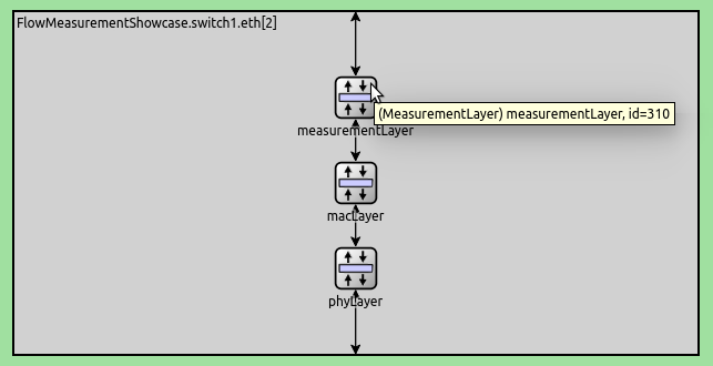
For the packet flow between the two switches, we can enable the built-in measurementLayer submodule of LayeredEthernetInterface:
*.switch*.eth[2].measurementLayer.typename = "MeasurementLayer"
Here is the complete flow definition configuration (including the definitions already mentioned):
*.client*.app[*].measurementStarter.typename = "FlowMeasurementStarter"
*.client1.app[0].measurementStarter.flowName = "c1s1"
*.client1.app[1].measurementStarter.flowName = "c1s2"
*.client1.app[*].measurementStarter.measure = "elapsedTime or queueingTime"
*.client2.app[0].measurementStarter.flowName = "c2s1"
*.client2.app[1].measurementStarter.flowName = "c2s2"
*.client2.app[*].measurementStarter.measure = "elapsedTime or queueingTime"

*.server*.app[*].measurementRecorder.typename = "FlowMeasurementRecorder"
*.server1.app[0].measurementRecorder.flowName = "c1s1 or c1s2 or c2s1 or c2s2"
*.server1.app[*].measurementRecorder.measure = "elapsedTime or queueingTime"
*.server2.app[0].measurementRecorder.flowName = "c1s1 or c1s2 or c2s1 or c2s2"
*.server2.app[*].measurementRecorder.measure = "elapsedTime or queueingTime"

*.switch*.eth[2].measurementLayer.typename = "MeasurementLayer"
*.switch1.eth[2].measurementLayer.measurementStarter.flowName = "sw1sw2"
*.switch1.eth[2].measurementLayer.measurementStarter.measure = "elapsedTime or queueingTime"
*.switch2.eth[2].measurementLayer.measurementRecorder.flowName = "sw1sw2"
*.switch2.eth[2].measurementLayer.measurementRecorder.measure = "elapsedTime or queueingTime"
We set up the four flows between the clients and the servers, and also the flow
between the two switches. We name flows based on source and destination node
(e.g. c1s1 for client1->server1). We set the measurement modules to
measure the elapsed time and the queueing time. Some notes:
The
sw1sw2flow is between the two switch interfaces facing each other (eth2in both switches), so that it’s unnecessary for the other switch interfaces to have measurement modules.- It is possible to record multiple flows in a FlowMeasurementRecorder, e.g.:
*.server1.app[*].inbound.flowName = "c1s1 or c1s2 or c2s1 or c2s2".
Note
We don’t specify any packet filter parameters of measurement modules, and they match all packets by default. We use packet filters in Example 2.
Results
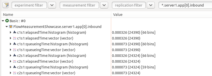
The measured timing data is available as a statistic of the measurement recorder
modules. For example, here are the statistics recorded from the measurements in
server1 (c1s1 and c2s1 flows), displayed in the browse data tab in
the Analysis Tool:
Example 2: Inserting New Measurement Modules
This simulation demonstrates the following:
Adding measurement modules to an arbitrary module
Assigning packets from multiple sources into the same flow
Assigning packets to flows based on port numbers
The simulation is defined in the AnyLocation config in omnetpp.ini.
Configuration
In this configuration, we want to demonstrate adding measurement modules to the network without using built-in ones. To do that, we want to group packets into packet flows below the Udp module in hosts. Compared to the previous configuration where each UDP app had its own flow, here packets from the two applications are mixed in the flows.
The easiest way to insert a measurement module into any module (which doesn’t
already have one built in) is to derive a new type extended with a measurement
module. For example, we extend StandardHost into MyStandardHost in
FlowMeasurementShowcase.ned. We could create two versions, one with a
FlowMeasurementStarter and one with a FlowMeasurementRecorder, but
it is more convenient (and more generic) to add a MeasurementLayer, which
contains both:
module MyStandardHost extends StandardHost
{
    submodules:
        measurementLayer: <default("")> like IMeasurementLayer {
            @display("p=450,250");
        }
    connections:
        udp.ipOut --> { @reconnect; } --> measurementLayer.upperLayerIn if hasUdp;
        measurementLayer.lowerLayerOut --> { @reconnect; } --> tn.in[0] if hasUdp;
        udp.ipIn <-- { @reconnect; } <-- measurementLayer.upperLayerOut if hasUdp;
        measurementLayer.lowerLayerIn <-- { @reconnect; } <-- tn.out[0] if hasUdp;
}
To make MyStandardHost even more generic, we make the measurement layer
module disabled by default. We can enable the measurement layer module from the
.INI file.
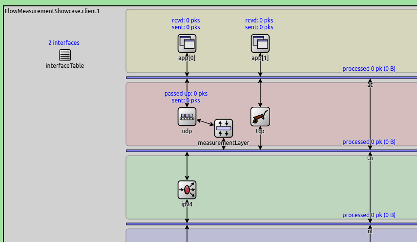
We insert the measurement layer module between the Udp module and the MessageDispatcher below it. The gates need to be reconnected to the new module (as per the connection section in the NED code above). Here is the result:
Now, we can use the MyStandardHost type in the .INI configuration:
*.client*.typename = "MyStandardHost"
*.server*.typename = "MyStandardHost"
We want to demonstrate grouping packets into multiple packet flows based on
source port. Our goal is to assign UDP packets with source port 500 to flow
VID, and those with source port 1000 to flow BG. To do that, we need two
FlowMeasurementStarter modules, each assigning packets to one of the
flows. We can simply use the MultiMeasurementLayer module in the hosts:
*.client*.measurementLayer.typename = "MultiMeasurementLayer"
*.server*.measurementLayer.typename = "MultiMeasurementLayer"

*.client*.measurementLayer.numMeasurementModules = 2
Note
One measurement recorder module is enough in the servers, as it can record both flows.
Here is the flow definition in omnetpp.ini:
*.client*.measurementLayer.measurementStarter[0].flowName = "VID"
*.client*.measurementLayer.measurementStarter[0].packetFilter = expr(has(udp) && udp.srcPort == 500)
*.client*.measurementLayer.measurementStarter[1].flowName = "BG"
*.client*.measurementLayer.measurementStarter[1].packetFilter = expr(has(udp) && udp.srcPort == 1000)
*.client*.measurementLayer.measurementStarter[*].measure = "elapsedTime or queueingTime"
*.client*.measurementLayer.measurementMaker[*].typename = ""

*.server*.measurementLayer.measurementMaker[0].flowName = "VID or BG"
*.server*.measurementLayer.measurementMaker[*].measure = "elapsedTime or queueingTime"
*.server*.measurementLayer.measurementStarter[*].typename = ""
The flow definition sets up two flows (BG and VID) based on the source
port of packets. The flows have multiple start and end points (in both clients
and servers, respectively). Each measurement module in MultiMeasurementLayer
assigns packets to one of the flows, using the packet data filter. As in the
previous configuration, we measure elapsed time and queueing time.
Note that:
A recorder records both flows independently
Packets from multiple sources that belong to the same flow are recorded in the same statistic
We don’t need the measurement recorders in the clients, and the measurement starters in the servers, so we disable them within the MultiMeasurementLayer module.
Results
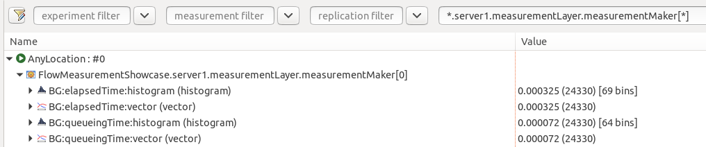
The measured elapsed time and queueing time values are available as the
statistics of the measurement recorder modules. For example, here are the two
elapsed time vectors (for the BG and VID flows) recorded as separate
statitics by the measurement recorder modules in server1, displayed in the
IDE’s analysis tool:
Sources: omnetpp.ini, FlowMeasurementShowcase.ned
Try It Yourself
If you already have INET and OMNeT++ installed, start the IDE by typing
omnetpp, import the INET project into the IDE, then navigate to the
inet/showcases/measurement/flow folder in the Project Explorer. There, you can view
and edit the showcase files, run simulations, and analyze results.
Otherwise, there is an easy way to install INET and OMNeT++ using opp_env, and run the simulation interactively.
Ensure that opp_env is installed on your system, then execute:
$ opp_env run inet-4.6 --init -w inet-workspace --install --build-modes=release --chdir \
   -c 'cd inet-4.6.*/showcases/measurement/flow && inet'
This command creates an inet-workspace directory, installs the appropriate
versions of INET and OMNeT++ within it, and launches the inet command in the
showcase directory for interactive simulation.
Alternatively, for a more hands-on experience, you can first set up the workspace and then open an interactive shell:
$ opp_env install --init -w inet-workspace --build-modes=release inet-4.6
$ cd inet-workspace
$ opp_env shell
Inside the shell, start the IDE by typing omnetpp, import the INET project,
then start exploring.
Discussion
Use this page in the GitHub issue tracker for commenting on this showcase.