Visualizing the Physical Environment
Goals
The physical environment has a profound effect on the communication of wireless devices. For example, physical objects like walls inside buildings constrain mobility. They also obstruct radio signals, often resulting in packet loss. It is difficult to make sense of the simulation without actually seeing where physical objects are. INET provides the visualization of these objects to help understand the simulation better. This feature is available both in 2D and 3D visualization.
This showcase demonstrates the visualization of physical objects through displaying the floorplan and walls of an apartment.
Note
This showcase requires OMNeT++ built with OSG enabled.
4.6About the visualizer
The PhysicalEnvironmentVisualizer (also part of IntegratedVisualizer) is responsible for displaying the physical objects. The objects themselves are provided by the PhysicalEnvironment module; their geometry, physical and visual properties are defined in the XML configuration of the PhysicalEnvironment module.
Note
For more information about the XML format in which the physical environment (geometry, materials, etc.) can be defined, see the NED documentation of the PhysicalEnvironment module.
The two-dimensional projection of physical objects is determined by the SceneCanvasVisualizer module (projection is also needed by other visualizers, for example, MobilityVisualizer). The default view is the top view (z-axis), but you can also configure side view (x and y axes), or isometric or orthographic projection.
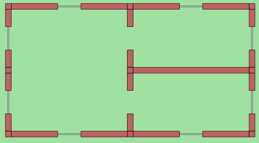
The default view
This example configuration (DefaultView in the ini file)
demonstrates the default visualization of objects. The objects are
defined in the indoor.xml file, which depicts an apartment with
three rooms. The network contains just two modules, a
PhysicalEnvironment and an IntegratedVisualizer module. When the
simulation is run, the network looks like this:
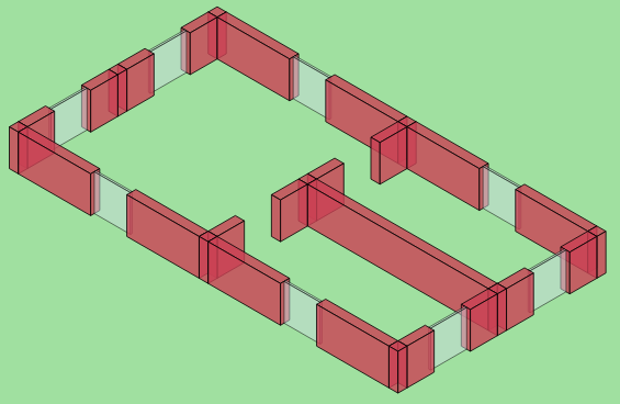
The isometric view
In this example configuration (IsometricView in the ini file), the
view is set to isometric projection by setting the
viewAngle parameter in SceneVisualizer:
*.visualizer.canvasVisualizer.sceneVisualizer.viewAngle = "isometric"
When the simulation is run, the network looks like the following.
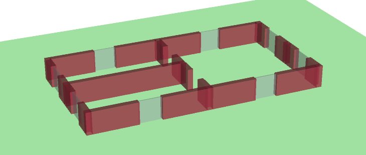
3D visualization
The visualizer also supports OpenGL-based 3D rendering using the OpenSceneGraph (OSG) library. If your OMNeT++ installation has been compiled with OSG support, you can switch to 3D view using the toolbar. The result will look like the following. Note that the SceneVisualizer view settings have no effect on the 3D view; you can use the mouse to move the camera and change the view angle.
Sources: omnetpp.ini, PhysicalEnvironmentVisualizationShowcase.ned
Further information
For more information, refer to the NED documentation of PhysicalEnvironmentVisualizer, SceneCanvasVisualizer and SceneOsgVisualizerBase.
Try It Yourself
First, install INET and OMNeT++. Then, start the IDE by typing
omnetpp, import the INET project into the IDE, then navigate to the
inet/showcases/visualizer/osg/environment folder in the Project Explorer. There, you can view
and edit the showcase files, run simulations, and analyze results.
Currently, opp_env-based installation is not available for the 3D visualization (OSG-based) showcases.
Discussion
Use this page in the GitHub issue tracker for commenting on this showcase.