Asynchronous Traffic Shaping
Goals
The Asynchronous Traffic Shaper (ATS), specified in IEEE 802.1Qcr, prioritizes and schedules traffic using per-class queuing and per-stream reshaping. Unlike time-aware shapers, ATS does not require network-wide coordinated time and avoids wasting allocated network bandwidth. It efficiently handles the mixture of various traffic patterns, including arbitrary periodic and sporadic traffic.
In this showcase, we will demonstrate how to use asynchronous traffic shaping in an Ethernet network focusing on the configuration and the operation of the model.
4.6The Model
Overview
The asynchronous traffic shaper operates by measuring the data rate of an incoming traffic stream and determining the transmission eligibility time for each packet. Once this eligibility time is reached, the packet is allowed to be sent, resulting in the formation of shaped output traffic. Transmission eligibility time can be calculated independently for multiple streams. However, since packets from these multiple streams may share the same queue, their respective transmission times can be affected by one another.
The transmission eligibility time is calculated by the asynchronous shaper algorithm. The shaper has two parameters that can be specified: the committed information rate, and the committed burst rate. The committed information rate is similar to the idle slope parameter of the credit-based shaper in that it specifies an average outgoing data rate that the traffic is limited to. The committed burst rate allows to temporarily increase the data rate above the limit. Additionally, a max residence time value can be specified. The shaper ensures that packets wait less than this time value in the queue, by dropping packets that would exceed it.
In INET, the asynchronous shaper is implemented by four modules, each having its place in the TSN node architecture:
EligibilityTimeMeter: calculates transmission eligibility time (in the ingress filter of the bridging layer)
EligibilityTimeFilter: filters out packets that would wait for too long in the queue (in the ingress filter of the bridging layer)
EligibilityTimeQueue: stores packets ordered by transmission eligibility time (in the network interface)
EligibilityTimeGate: prevents packets from passing through the gate before the transmission eligibility time (in the network interface)
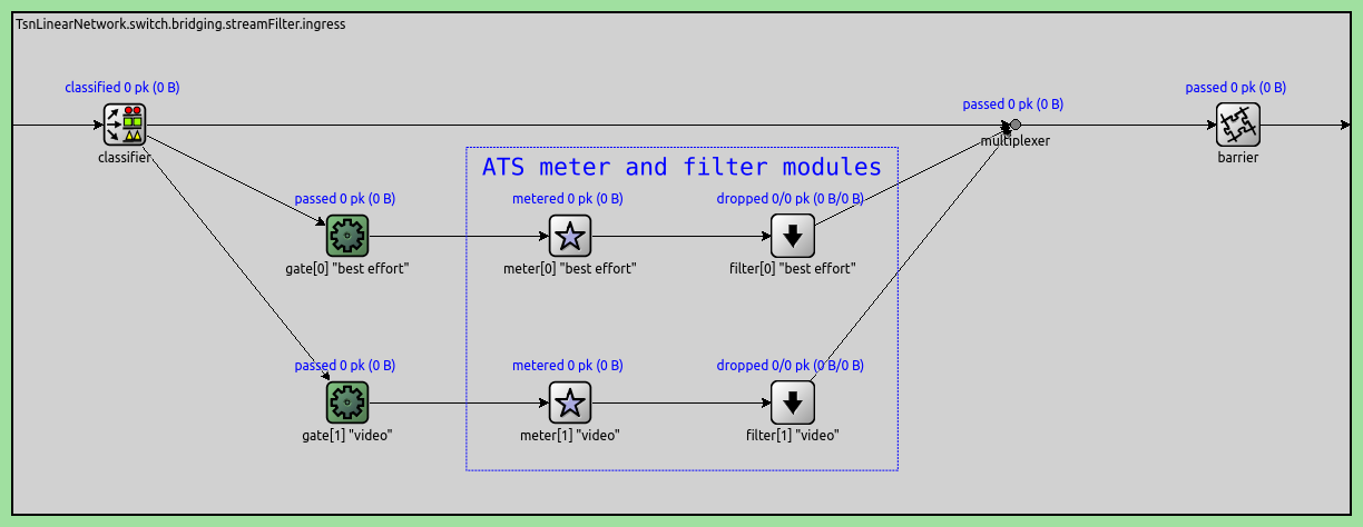
For context, here are the meter and filter modules in the bridging layer (bridging.streamFilter.ingress):
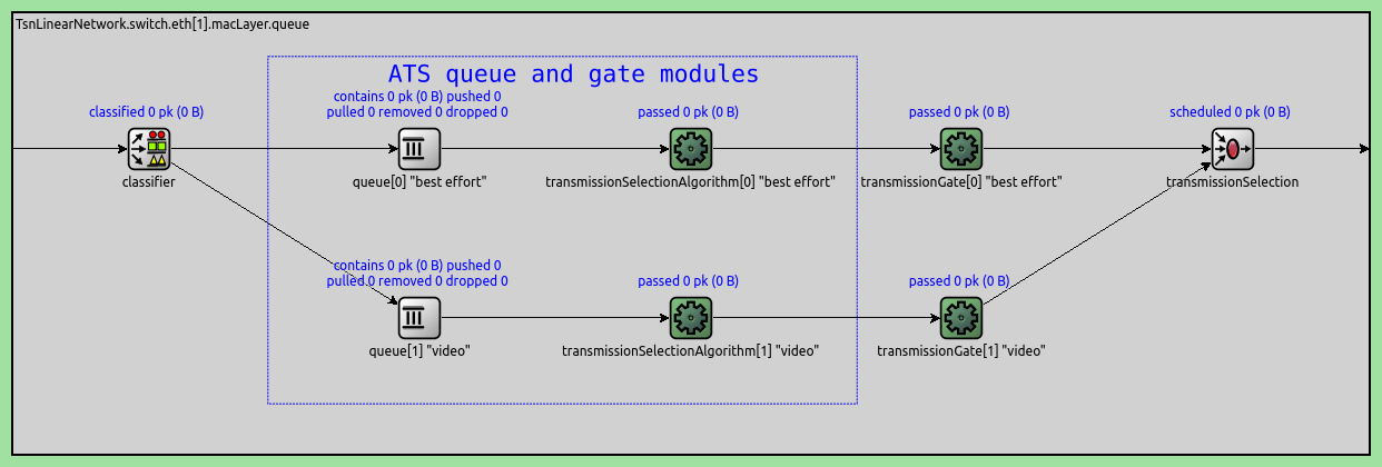
Here are the queue and gate modules in the network interface (eth[*].macLayer.queue):
To enable asynchronous traffic shaping in a TSN switch, the following is required:
Enable ingress traffic filtering in the switch (this adds a StreamFilterLayer to the bridging layer):
*.switch.hasIngressTrafficFiltering = trueSet the type of the meter and filter submodules in
streaminglayer.ingressfilter:*.switch.bridging.streamFilter.ingress.meter[*].typename = "EligibilityTimeMeter"*.switch.bridging.streamFilter.ingress.filter[*].typename = "EligibilityTimeFilter"Enable egress traffic shaping in the switch (this adds a Ieee8021qTimeAwareShaper to all network interfaces):
*.switch.hasEgressTrafficShaping = trueSet the type of the
queueandtransmissionSelectionAlgorithmsubmodules ineth[*].macLayer.queue:*.switch.eth[*].macLayer.queue.queue[*].typename = "EligibilityTimeQueue"*.switch.eth[*].macLayer.queue.transmissionSelectionAlgorithm[*].typename = "EligibilityTimeGate"We can override the number of traffic classes (8 by default) in the time-aware shaper modules (
eth[*].macLayer.queue):*.switch.eth[*].macLayer.queue.numTrafficClasses = 2To configure the asynchronous traffic shaping, set the following parameters of EligibilityTimeMeter:
committedInformationRateandcommittedBurstSize: These parameters specify the nominal outgoing data rate and the allowed burst size of the shaper.maxResidenceTime: Packets are dropped by the EligibilityTimeFilter if the simulation time equalseligibility time + max residence time(not used by default).
The Configuration
Network
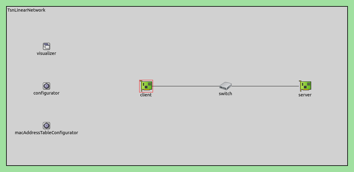
The network contains three network nodes. The client and the server (TsnDevice) are connected through the switch (TsnSwitch), with 100Mbps EthernetLink channels:
Overview
Similarly to the Credit-Based Shaping showcase, we configure the client to generate two streams of fluctuating traffic, and to assign them to two different traffic categories. We add asynchronous traffic shapers to the switch that smooths outgoing traffic for each traffic category independently.
Traffic
Similarly to the Time-Aware Shaping and Credit-Based Shaping showcases, we want to observe only the effect of the asynchronous shaper on the traffic. Thus our goal is for the traffic to only get altered in the traffic shaper, and avoid any unintended traffic shaping effect in other parts of the network.
Traffic configuration is the same as the Credit-Based Shaping showcase. We configure two traffic source applications in the client, creating two independent data streams between the client and the server. The data rate of the streams fluctuates randomly around 40 and 20 Mbps mean values, respectively, but the links in the network are not saturated. Later on, we configure the traffic shaper to limit the data rate to the nominal values of 40 and 20 Mbps for the data streams. Here is the traffic configuration:
# client applications
*.client.numApps = 2
*.client.app[*].typename = "UdpSourceApp"
*.client.app[0].display-name = "best effort"
*.client.app[1].display-name = "video"
*.client.app[*].io.destAddress = "server"
*.client.app[0].io.destPort = 1000
*.client.app[1].io.destPort = 1001
*.client.app[*].source.packetLength = 1000B

*.client.app[0].source.productionInterval = replaceUnit(1 / (sin(dropUnit(simTime()) * 3) + 5), "ms")	# avg 200us/40Mbps
*.client.app[1].source.productionInterval = replaceUnit(1 / (sin(dropUnit(simTime() * 1)) + sin(dropUnit(simTime() * 8)) + 2.5), "ms")	# avg 400us/20Mbps

# server applications
*.server.numApps = 2
*.server.app[*].typename = "UdpSinkApp"
*.server.app[0].display-name = "best effort"
*.server.app[1].display-name = "video"
*.server.app[0].io.localPort = 1000
*.server.app[1].io.localPort = 1001
Stream Identification and Encoding
We classify packets to the two traffic categories (best effort and video) the same way as in the Credit-Based Shaping showcase. To summarize:
In the client:
We enable IEEE 802.1 stream identification and stream encoding.
We configure the stream identifier module in the bridging layer to assign outgoing packets to named streams by UDP destination port.
We configure the stream encoder to set the PCP number according to the assigned stream name.
In the switch:
We disable the forwarding of 802.1Q C-tags. The server doesn’t have a Ieee8021qProtocol module, and would otherwise drop all packets due to unknown protocol.
We configure the stream decoder to decode the streams by the PCP number.
Here is the relevant configuration:
# enable outgoing streams
*.client.hasOutgoingStreams = true

# client stream identification
*.client.bridging.streamIdentifier.identifier.mapping = [{stream: "best effort", packetFilter: expr(udp.destPort == 1000)},
                                                         {stream: "video", packetFilter: expr(udp.destPort == 1001)}]

# client stream encoding
*.client.bridging.streamCoder.encoder.mapping = [{stream: "best effort", pcp: 0},
                                                 {stream: "video", pcp: 4}]

# disable forwarding IEEE 802.1Q C-Tag
*.switch.bridging.directionReverser.reverser.excludeEncapsulationProtocols = ["ieee8021qctag"]

# switch stream decoding
*.switch.bridging.streamCoder.decoder.mapping = [{pcp: 0, stream: "best effort"},
                                                 {pcp: 4, stream: "video"}]
Asynchronous Traffic Shaping
Per-Stream Filtering
Next, we need to add the EligibilityTimeMeter and EligibilityTimeFilter modules to the bridging layer of the switch, and configure them:
Enable ingress per-stream traffic filtering in the switch (as described above, this adds a StreamFilterLayer to the switch; the stream filtering layer has an ingress filter (SimpleIeee8021qFilter) submodule that we configure to contain the eligibility-time meters and filters).
As we want per-stream filtering, we configure two traffic streams in the ingress filter.
Configure the mapping in the classifier (StreamClassifier) in the ingress filter. This tells the classifier to send “best effort” streams to gate 0, and video streams to gate 1.
Override the type of the
metersubmodules with EligibilityTimeMeter, and configure the committed information rate and committed burst size parameters. Also, we set a max residence time of 10ms in the meter; this ensures that packets waiting more than 10ms in the switch are dropped by the filter submodule that we configure next.Override the type of the
metersubmodules with EligibilityTimeFilter.
Here is the configuration doing the above:
# enable ingress per-stream filtering
*.switch.hasIngressTrafficFiltering = true

# per-stream filtering
*.switch.bridging.streamFilter.ingress.numStreams = 2
*.switch.bridging.streamFilter.ingress.classifier.mapping = {"best effort": 0, "video": 1}
*.switch.bridging.streamFilter.ingress.*[0].display-name = "best effort"
*.switch.bridging.streamFilter.ingress.*[1].display-name = "video"
*.switch.bridging.streamFilter.ingress.meter[*].typename = "EligibilityTimeMeter"
*.switch.bridging.streamFilter.ingress.meter[*].maxResidenceTime = 100ms
*.switch.bridging.streamFilter.ingress.meter[0].committedInformationRate = 41.68Mbps		# shaper data rate
*.switch.bridging.streamFilter.ingress.meter[0].committedBurstSize = 100 * (1000B + 28B)
*.switch.bridging.streamFilter.ingress.meter[1].committedInformationRate = 20.84Mbps		# shaper data rate
*.switch.bridging.streamFilter.ingress.meter[1].committedBurstSize = 50 * (1000B + 28B)
*.switch.bridging.streamFilter.ingress.meter[*].packetOverheadLength = 18B		# 1046-1028 (14 MAC header + 4 FCS)

*.switch.bridging.streamFilter.ingress.filter[*].typename = "EligibilityTimeFilter"
Thus far, we have two traffic categories encoded with PCP numbers and named streams, the meter calculates the eligibility time as per the parameters, and the filter drops any expired packets. Now we just need to add the necessary queues and gates.
Egress Traffic Shaping
The traffic shaping takes place in the outgoing network interface of the switch where both streams pass through. The EligibilityTimeQueue sorts the packets by eligibility time, and the EligibilityTimeGate prevents them from being sent before the eligibility time. The result is that the data rate of the best effort stream is limited to ~40 Mbps and that of the video stream to ~20 Mbps. The excess traffic is stored in the EligibilityTimeQueue submodules of the corresponding traffic class.
We enable egress traffic shaping in the switch, this adds the time-aware shaper modules to interfaces. We configure two traffic classes in the time-aware shapers, and set the subqueue and transmission selection algorithm submodule types:
# enable egress traffic shaping
*.switch.hasEgressTrafficShaping = true

# asynchronous traffic shaping
*.switch.eth[*].macLayer.queue.numTrafficClasses = 2
*.switch.eth[*].macLayer.queue.*[0].display-name = "best effort"
*.switch.eth[*].macLayer.queue.*[1].display-name = "video"
*.switch.eth[*].macLayer.queue.queue[*].typename = "EligibilityTimeQueue"
*.switch.eth[*].macLayer.queue.transmissionSelectionAlgorithm[*].typename = "EligibilityTimeGate"
Results
Let’s examine how the traffic data rate changes in the network, from the client to the server. The first chart displays the data rate of the client application and the incoming traffic of the shaper’s filter module, per-stream:
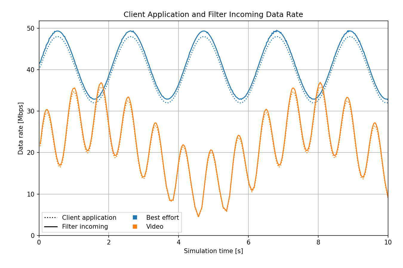
The data rate of the client is sinusoidal for both traffic classes, with the average values of 42 and 21 Mbps. For each stream, the client application traffic and the incoming traffic in the shaper’s filter module is similar. The data rate is higher in the filter because it already includes protocol overhead, such as the Ethernet header.
The next chart compares the incoming, outgoing, and dropped traffic in the filter, so we can observe how the traffic changes. The committed information rate (configured in the meter modules) is displayed with the two dash-dotted lines:
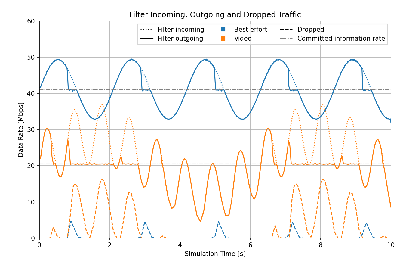
Initially, outgoing traffic is equal to incoming traffic. However, around the 1-second mark, packet loss begins to occur, resulting in a decrease in outgoing traffic. This is due to the filter, which drops packets that would exceed the configured maximum residence time while waiting in the queue for transmission.
This filtering mechanism effectively establishes a virtual queue length limit, as it imposes an upper bound on the queuing time. When the queue length approaches this virtual limit, any additional packets are discarded to prevent excessive wait times. In this case, the filter outgoing data rate equals the committed information rate minus some protocol headers.
The next chart displays the queue incoming and outgoing (already shaped) traffic:
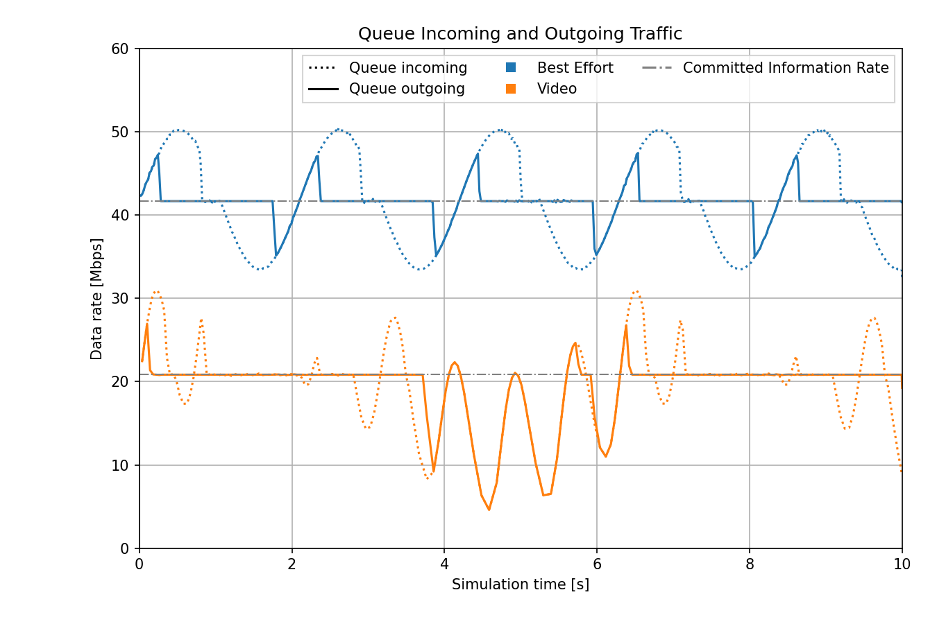
The shaper allows some bursts, but in general, limits the outgoing traffic to the committed information rate using the transmission eligibility time.
The next chart displays the shaper outgoing and the server application traffic data rate:
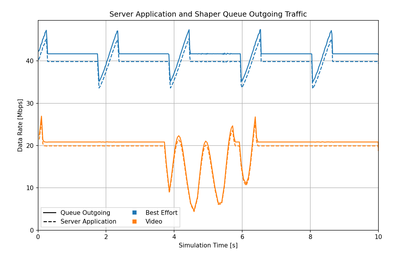
The traffic doesn’t change significantly in this part of the network. Again, the shaper data rate is slightly higher due to protocol overhead. Thus, as per our goal, traffic is only altered significantly in the shaper components (filter and queue).
The following two charts give an overview of how traffic changes in the filter and queue modules, with the queue length displayed as well:
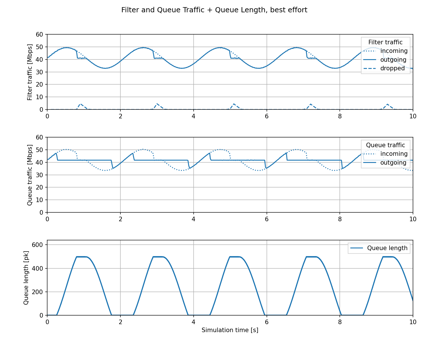
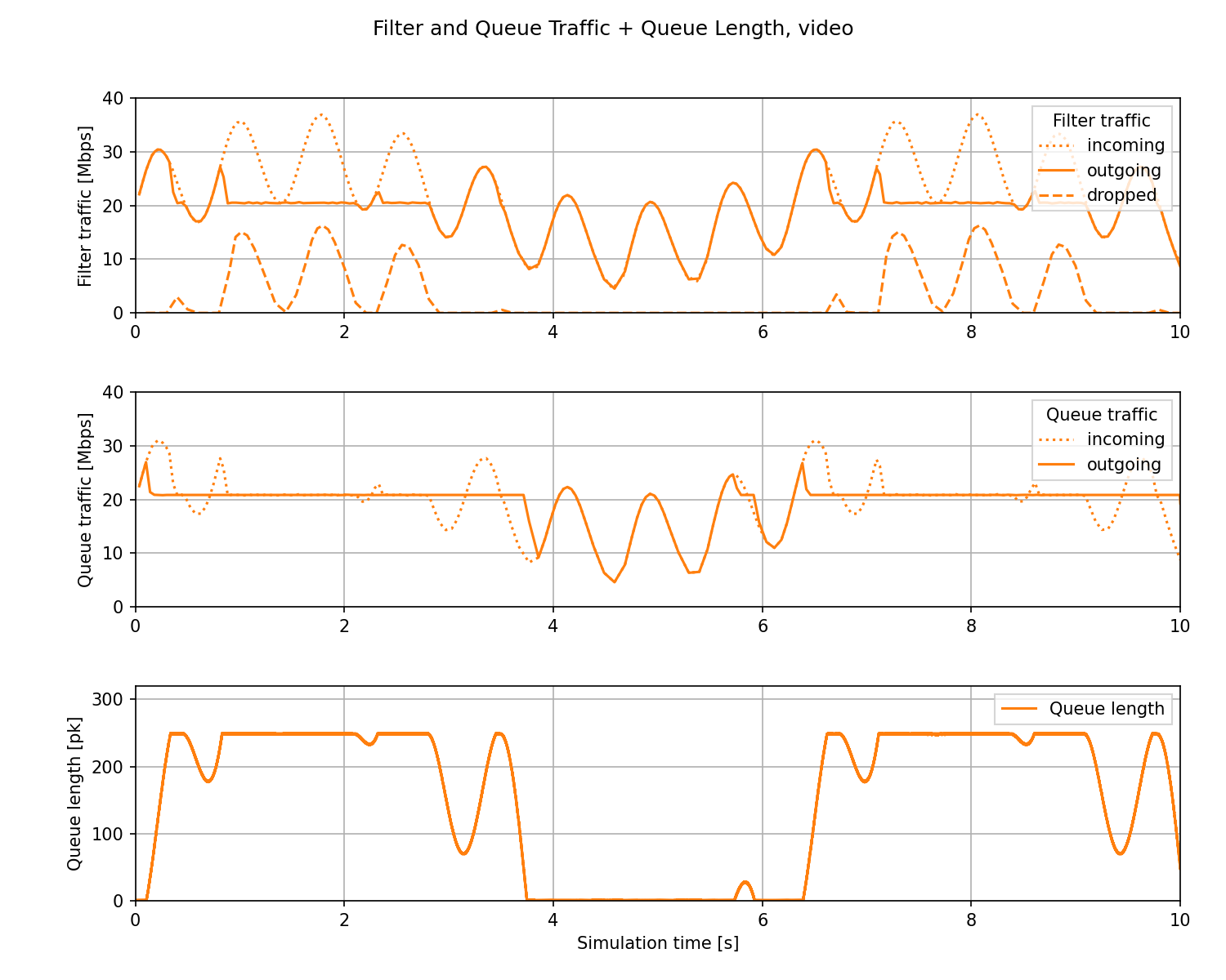
We can observe that packets get dropped when the virtual queue limit is reached. Also, the queue length is zero when the traffic is low.
The following is a zoomed-in chart displaying the queue incoming and outgoing traffic. We can observe the operation of the filter and traffic shaping in the queue:
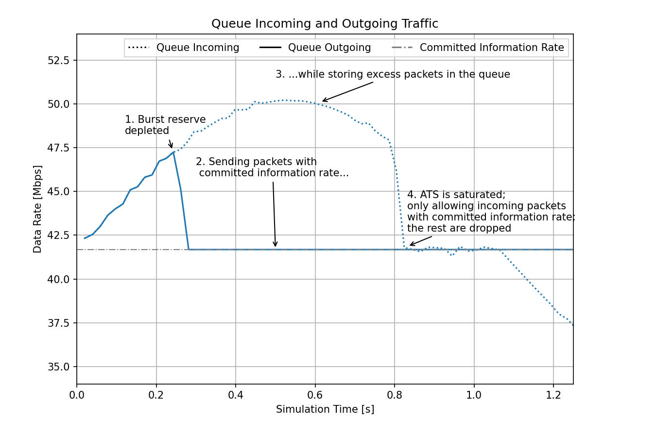
At the beginning, the shaper has a burst reserve available, so all incoming packets are sent immediately. When the burst reserve is depleted, the shaper starts limiting the outgoing data rate to the committed information rate. Meanwhile, the excess incoming traffic is being stored in the queue. As described previously, the queue has a virtual limit, as packets that would wait more than the configured max residence time are dropped by the filter. When the queue is saturated (i.e., it reaches this virtual limit), traffic can only flow into the queue at the same rate as it flows out. Outgoing traffic is limited to the committed information rate by traffic shaping, and incoming traffic is limited to this same value by the filter dropping excess traffic. When the incoming traffic decreases below this value, all packets are stored again. The outgoing traffic is still at the committed information rate as packets are transmitted from the queue.
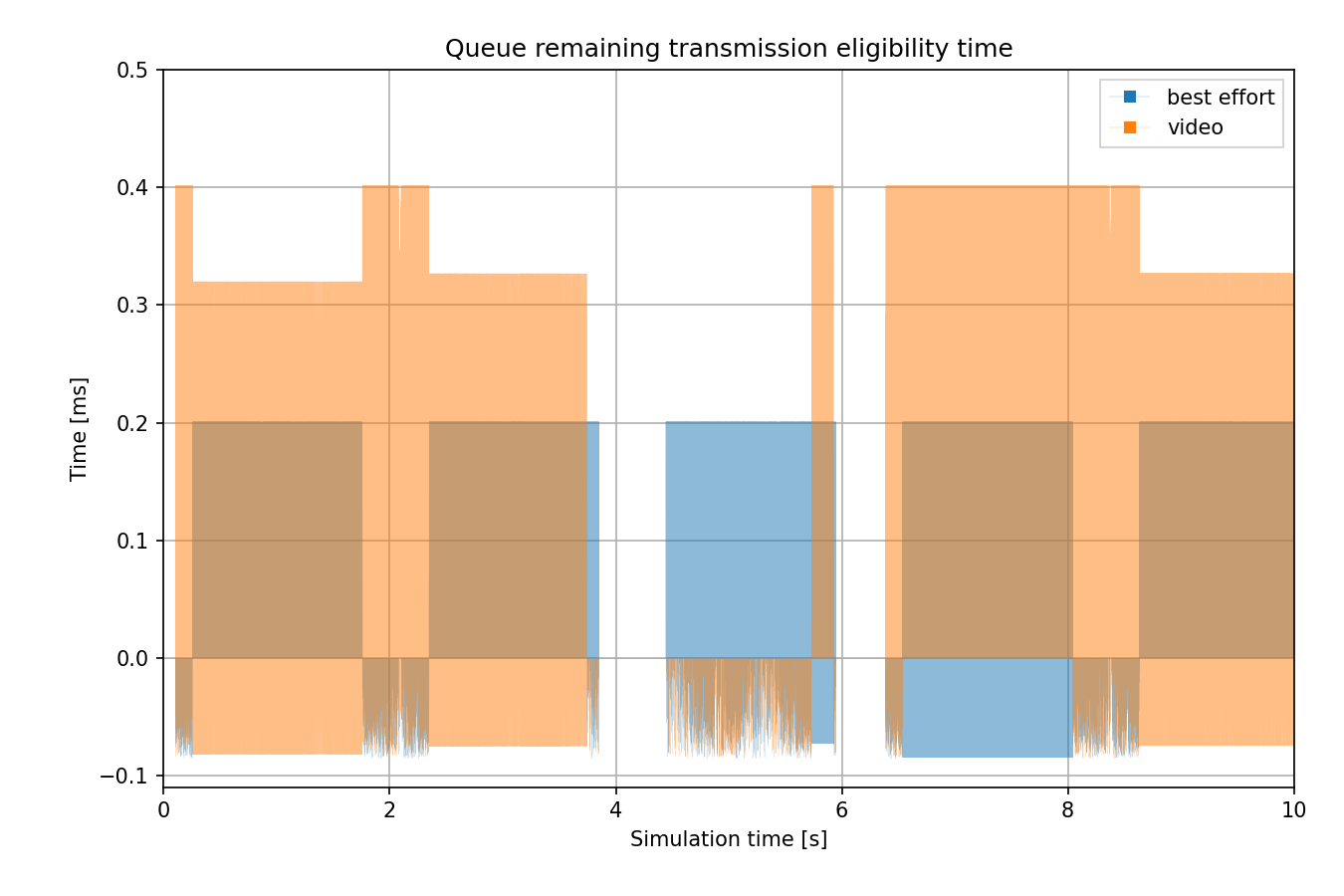
The next chart displays the remaining transmission eligibility time for the first packet in the queue:
Here is the same chart zoomed in:
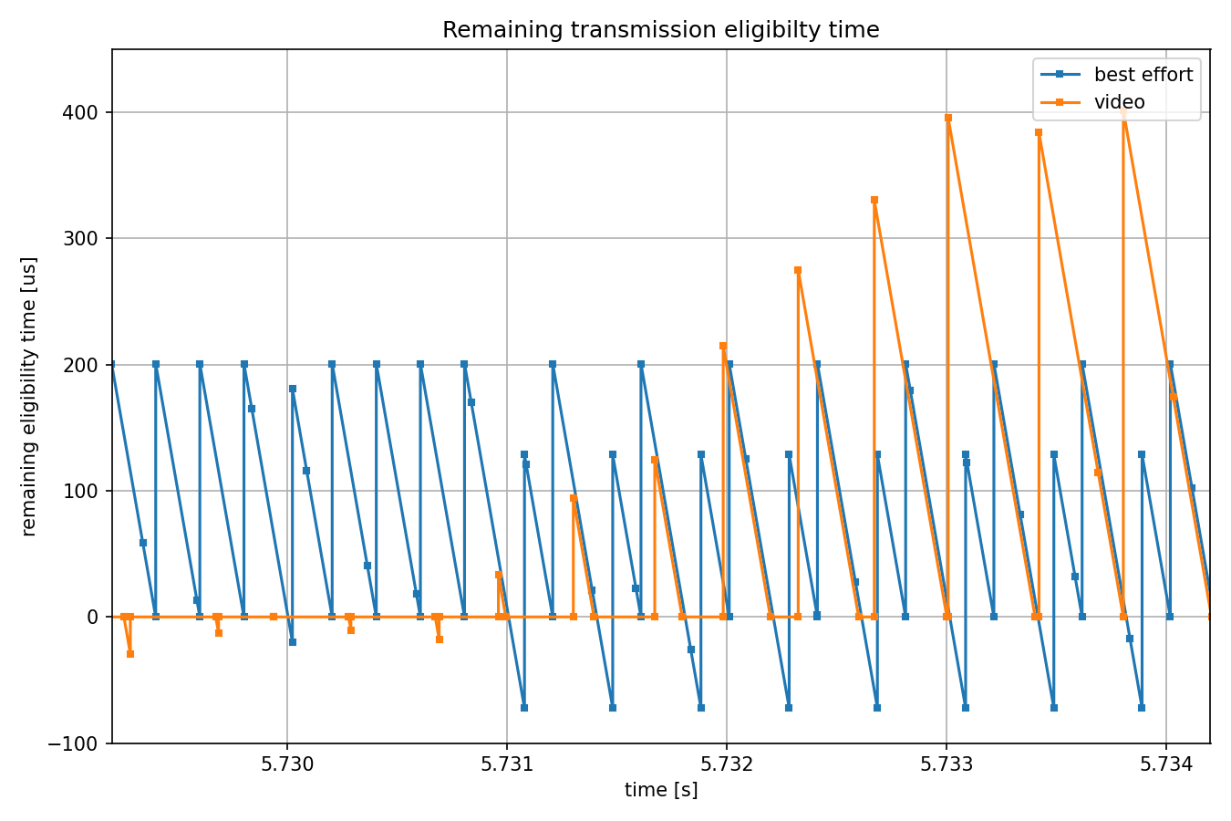
When the line is above the X-axis, the queue is blocked. When a line crosses the X-axis from above, the first packet in the queue becomes eligible for transmission. When the line goes below the X-axis, the first packet waits more than what is absolutely necessary. This can happen due to a higher priority traffic class using the channel, as is the case for every other best effort packet on the right side of the chart. It can also happen for higher-priority packets occasionally, because there is no frame preemption.
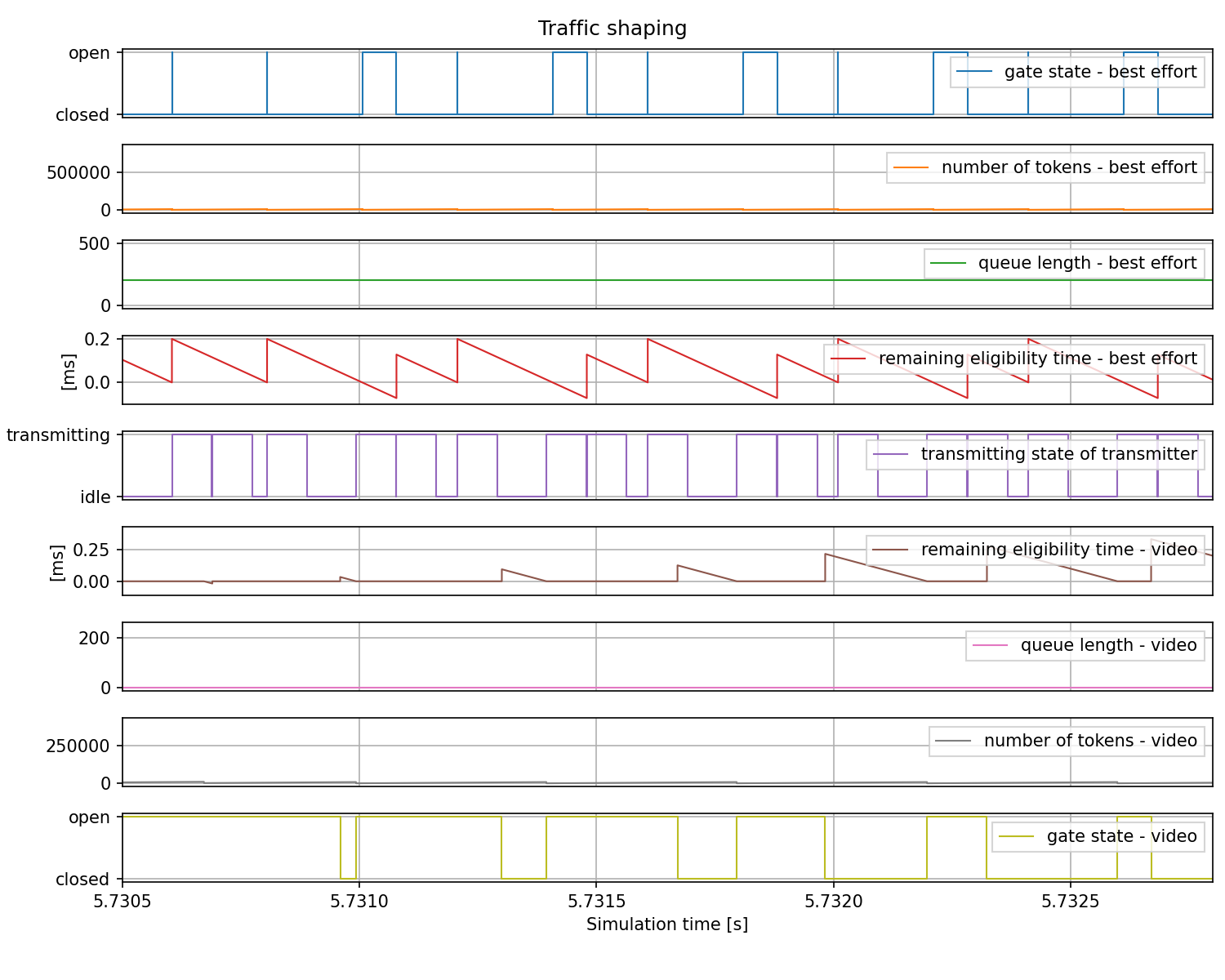
The following chart connects all the statistics presented above:
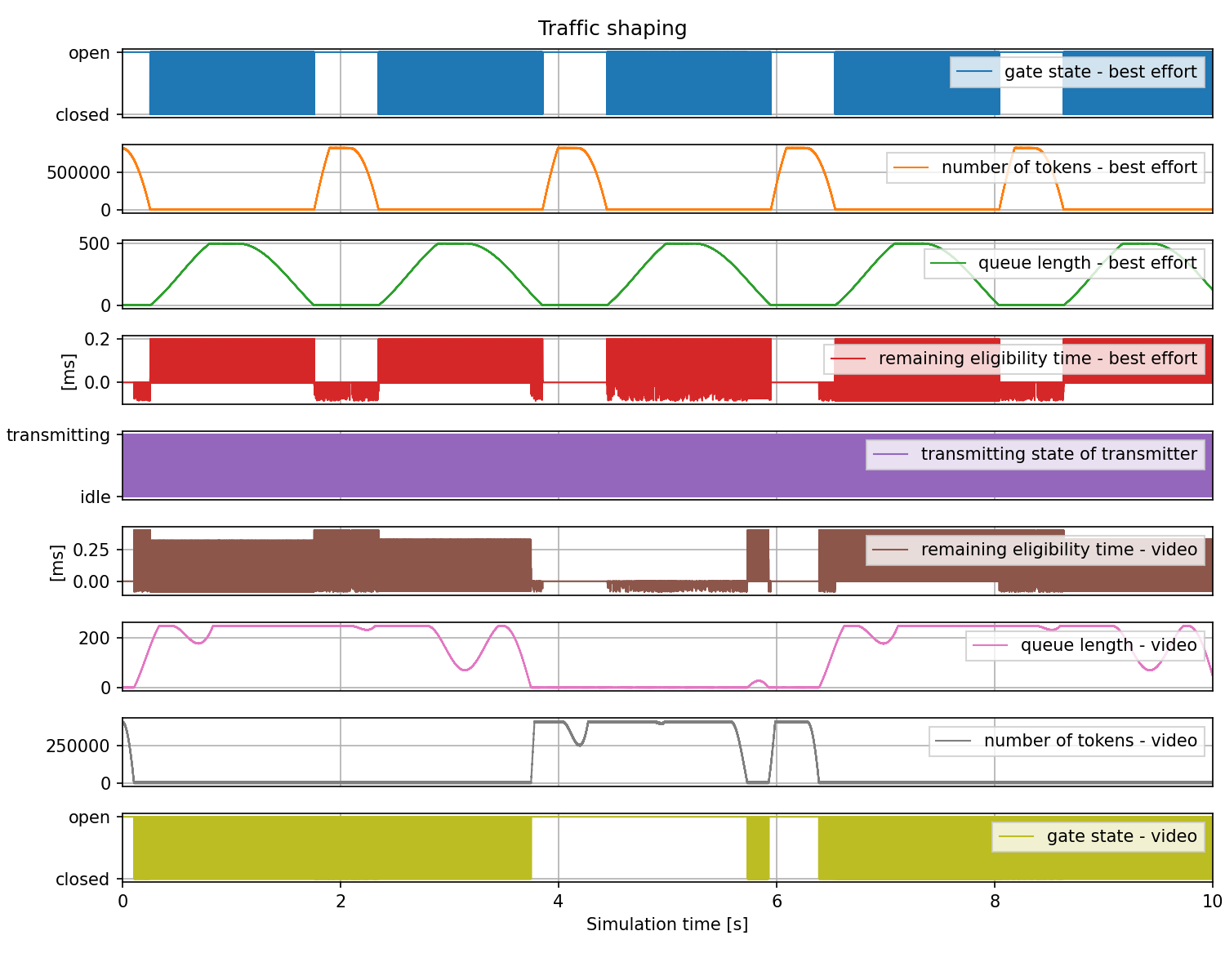
Here is the same chart zoomed in:
Sources: omnetpp.ini
Try It Yourself
If you already have INET and OMNeT++ installed, start the IDE by typing
omnetpp, import the INET project into the IDE, then navigate to the
inet/showcases/tsn/trafficshaping/asynchronousshaper folder in the Project Explorer. There, you can view
and edit the showcase files, run simulations, and analyze results.
Otherwise, there is an easy way to install INET and OMNeT++ using opp_env, and run the simulation interactively.
Ensure that opp_env is installed on your system, then execute:
$ opp_env run inet-4.6 --init -w inet-workspace --install --build-modes=release --chdir \
   -c 'cd inet-4.6.*/showcases/tsn/trafficshaping/asynchronousshaper && inet'
This command creates an inet-workspace directory, installs the appropriate
versions of INET and OMNeT++ within it, and launches the inet command in the
showcase directory for interactive simulation.
Alternatively, for a more hands-on experience, you can first set up the workspace and then open an interactive shell:
$ opp_env install --init -w inet-workspace --build-modes=release inet-4.6
$ cd inet-workspace
$ opp_env shell
Inside the shell, start the IDE by typing omnetpp, import the INET project,
then start exploring.
Discussion
Use this page in the GitHub issue tracker for commenting on this showcase.