IEEE 802.11 Frame Aggregation
Goals
IEEE 802.11 frame aggregation is a feature that can improve the performance of wireless networks by reducing the overhead associated with transmitting small packets. When sending small packets over a wireless network using the 802.11 protocol, the overhead from protocol headers and other control information can become significant, resulting in reduced performance. Frame aggregation helps to mitigate this performance hit by allowing multiple data packets to be sent in a single 802.11 transmission. This reduces the number of contention periods, interframe spaces, and protocol headers, increasing the overall throughput of the network.
In this showcase, we will demonstrate frame aggregation in INET’s 802.11 model and examine its effect on performance when sending a large number of small packets.
4.0About Aggregation
Frame aggregation increases throughput by sending multiple data frames in a single transmission. It reduces 802.11 protocol overhead, as multiple packets can be sent with a single PHY and MAC header, instead of each packet having its own headers. The number of ACKs and interframe spaces (and contention periods, if not in a TXOP) is also reduced.
There are two kinds of frame aggregation in 802.11:
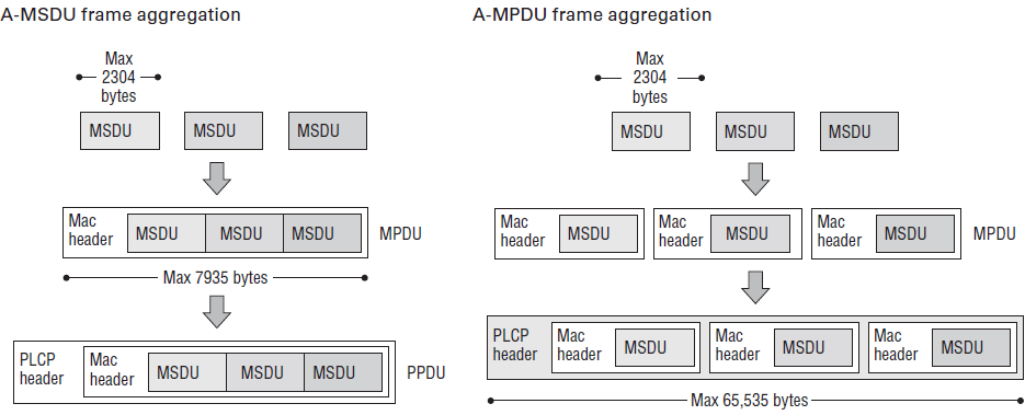
MAC Service Data Unit (MSDU) aggregation: the packets received by the MAC from the upper layer are MSDUs. Each packet gets an MSDU subframe header. Two or more subframes are bundled together and put in an 802.11 MAC frame (header + trailer). The resulting frame is an aggregate-MSDU (a-MSDU). The a-MSDUs are transmitted with a single PHY header by the radio.
MAC Protocol Data Unit (MPDU) aggregation: MPDUs are frames passed from the MAC to the PHY layer. Each MPDU has a MAC header and trailer. Multiple MPDU-s are bundled together to create an aggregate MPDU (a-MPDU), which is transmitted with a PHY header by the radio.
When using aggregation, the reduced number of contention periods, interframe spaces and ACKs might have a greater effect on performance than the shorter headers. In this regard, there might not be much difference between MSDU and MPDU aggregation.
MSDU aggregation has less overhead than MPDU aggregation. Each packet in an a-MSDU has an MSDU subframe header, but the aggregate frame has just one MAC header. In contrast, in a-MPDUs, each data packet has a MAC header. (The MAC header + trailer is 30B, the MSDU subframe header is 14B.)
Thus, a-MPDUs have more overhead, but each data packet has its own Frame check sequence (FCS) contained in the MAC trailer (in contrast with a-MSDUs, which have just one FCS for the whole aggregate frame). This way, the individual data packets sent in the a-MPDU can be acknowledged with a block acknowledgment frame, making MPDU aggregation more useful in a high error rate environment (the performance gain from using a-MSDUs might be negated by the higher error rate in a such an environment). Because a-MSDUs lack a global FCS, they can only be acknowledged with block ACKs.
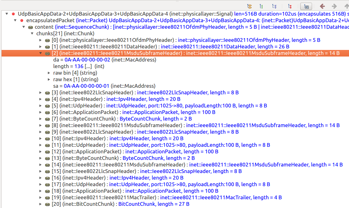
Here is an a-MSDU of three subframes displayed in qtenv’s packet view:
INET’s 802.11 model currently only features MSDU aggregation. Aggregation is
controlled by the aggregation policy in Ieee80211Mac. The aggregation
policy is a submodule of the MAC’s Hcf submodule. The aggregation policy
submodule is located at mac.hcf.originatorMacDataService.msduAggregationPolicy
in the module hierarchy. By default,
the Hcf module contains a BasicMsduAggregationPolicy submodule.
Aggregation can be controlled by the following parameters of BasicMsduAggregationPolicy:
subframeNumThreshold: Specifies the minimum number of frames needed to create an a-MSDU. By default, the number of frames is not checked. Thus, the MAC creates an a-MSDU from any number of packets present in the queue when the MAC decides to transmit.aggregationLengthThreshold: Specifies the minimum length for an aggregated payload needed to create an a-MSDU. By default, the length is not checked.maxAMsduSize: Specifies the maximum size for an a-MSDU. By default, its 4065 bytes.
When the MAC creates an a-MSDU, the resulting a-MSDU complies with all three of these parameters (if it didn’t comply with any of them, then no a-MSDU would be created, and the frames would be sent without aggregation).
To summarize, by default, the MAC aggregates frames when using HCF
(qosStation = true in the MAC). It aggregates any number of packets
present in the queue at the time it decides to transmit, making sure
the aggregated frame’s length doesn’t exceed 4065 bytes. By default,
the MAC doesn’t aggregate when using DCF.
The Model
In the example simulation for this showcase, a host sends small UDP packets to another host via 802.11. We will run the simulation with and without aggregation (and also with and without the use of TXOP), and examine the number of received packets, the application-level throughput and the end-to-end delay.
The Network
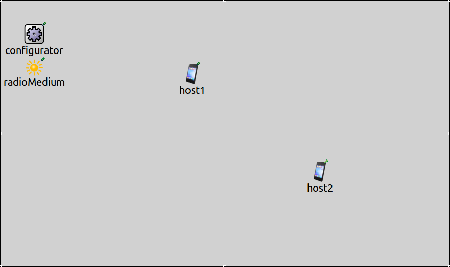
The simulation uses the following network, defined in
AggregationShowcase.ned:
It contains two AdhocHost’s, host1 and host2.
It also contains an Ipv4NetworkConfigurator and an
Ieee80211ScalarRadioMedium module.
Configurations
host1 is configured to send small, 100-byte UDP packets to host2.
Here are the traffic settings in the General configuration in
omnetpp.ini:
*.host1.numApps = 1
*.host1.app[0].typename = "UdpBasicApp"
*.host1.app[0].destAddresses = "host2"
*.host1.app[0].destPort = 80
*.host1.app[0].messageLength = 100Byte

*.host2.numApps = 1
*.host2.app[0].typename = "UdpSink"
*.host2.app[0].localPort = 80
Here are the 802.11 settings in the General configuration in
omnetpp.ini:
*.host*.wlan[*].opMode = "g(erp)"
*.host*.wlan[*].bitrate = 54Mbps
*.host*.wlan[*].classifier.typename = "QosClassifier"
*.host*.wlan[*].mac.qosStation = true
We set the mode to 802.11g ERP mode and 54 Mbps to increase the data transfer rate.
Note that the qosStation = true key makes the MAC use HCF, but a classifier
is also needed in order for the MAC to create QoS frames (required for aggregation).
There are three scenarios, defined in the following configurations, in a progression to improve throughput:
NoAggregation: Aggregation is turned off, the MAC sends UDP packets in the best effort access category (no TXOP). This configuration functions as a baseline to compare the effects of aggregation to. We expect that when no aggregation is used, throughput will be low because of the small packets and the large protocol overhead.Aggregation: Aggregation is on, and the MAC sends UDP packets in the best effort access category. Throughput is expected to increase substantially.VoicePriorityAggregation: Aggregation is on, and the MAC sends UDP packets in the voice access category in a TXOP. The use of TXOP reduces contention periods; throughput is expected to increase even further.
In all cases with aggregation, we use MSDU aggregation.
To negate the effect of queue length on the delay of packets, we set the amount of traffic to match the possible throughput in each configuration. This way we can concentrate on the effect aggregation has on the delay. (We measured the maximum possible throughput by running the simulations with very high traffic.)
Here is the NoAggregation configuration in omnetpp.ini:
[Config NoAggregation]

*.*.wlan[*].mac.hcf.originatorMacDataService.msduAggregationPolicy.typename = ""

*.host1.app[0].sendInterval = 0.3125ms
The configuration turns off aggregation.
Here is the Aggregation configuration in omnetpp.ini:
[Config Aggregation]

*.*.wlan[*].mac.hcf.originatorMacDataService.msduAggregationPolicy.maxAMsduSize = 1500

*.host1.app[0].sendInterval = 0.0727ms
Aggregation is turned on by default. This configuration sets the aggregated frame size to 1500B, so that the small packets are aggregated into a 1500B frame.
Here is the VoicePriorityAggregation in omnetpp.ini:
[Config VoicePriorityAggregation]
extends = Aggregation

**.*Port = 5000

*.host1.app[0].sendInterval = 0.038095ms
To ensure that the UDP packets belong to the voice priority access category, the UDP app’s source port is set to 5000 (the default port for voice priority in QosClassifier).
Results
Number of received packets and throughput
We run the simulations for 10 seconds.
We measure the number of packets received by host2, and the application-level throughput.
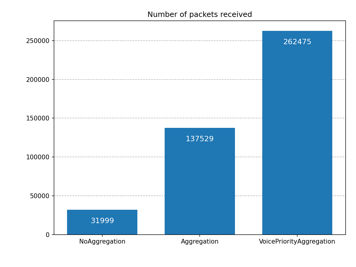
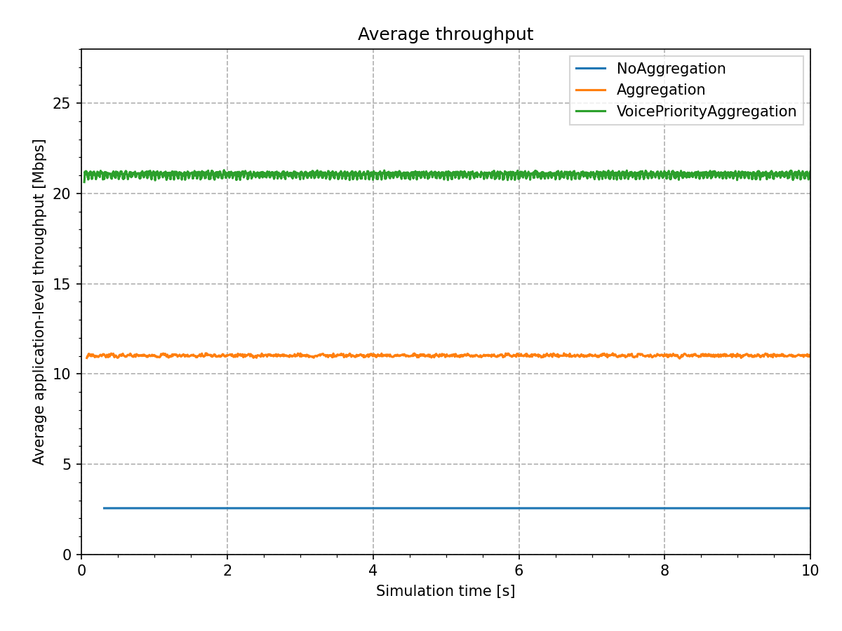
Here are the results from the simulations:
As expected, the throughput is low in the NoAggregation case, about 2.5 Mbps.
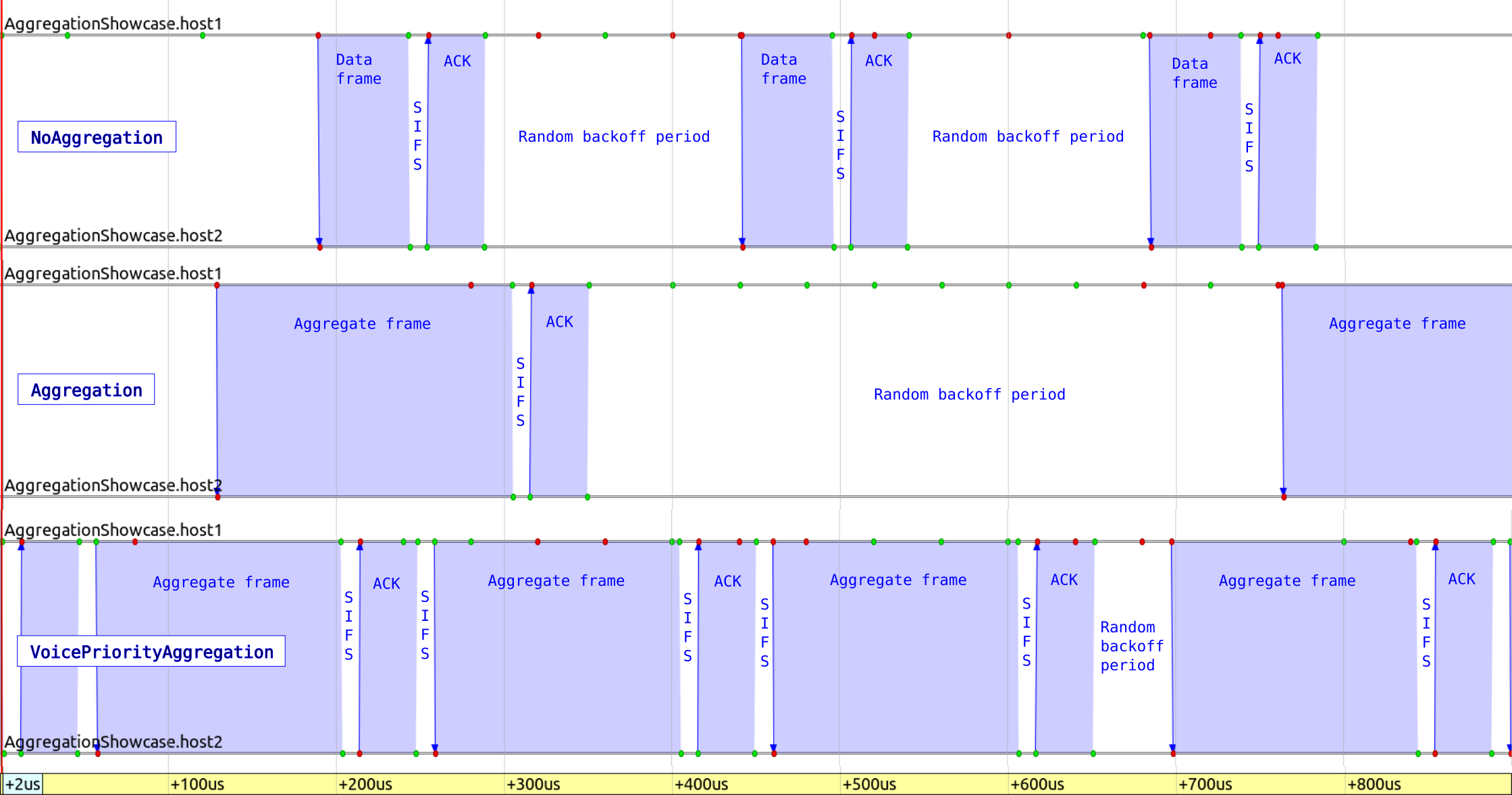
Each 100-byte UDP packet has an IP header, an LLC header, a MAC header, a MAC trailer,
and a PHY header. The MAC contends for the channel before sending each packet.
There is a SIFS period and an ACK after each packet transmission.
These amount to a lot of overhead.
In the Aggregation case, throughput increases by more than 400% (compared to
the NoAggregation case), to about 11 Mbps.
In this case, multiple (up to ten) 100-byte UDP packets are aggregated into a single 802.11
frame. Each UDP packet has an IP header, an LLC header, and an MSDU subframe header,
but the whole aggregate frame has just one MAC header and MAC trailer, and PHY header,
so overhead is smaller. Also, there is no contention between the subframes
(the MAC still has to contend for channel access before transmitting the aggregate frame).
There is also a SIFS period and an ACK after each packet transmission (though there
are less of these compared to the previous case, as ten packets are acknowledged with an ACK).
In the VoicePriorityAggregation, throughput increases by another 190%
(compared to the Aggregation case), to about 21Mbps. The MAC doesn’t have
to contend for channel access during the TXOP, which decreases overhead even more.
The following image shows frame exchanges for the three configurations on a sequence chart, on the same time scale:
End-to-end delay
In this section, we examine how aggregation affects the end-to-end delay of packets. The length of packet queues in the MAC can significantly affect delay, as packets can wait in the queue for some time before being sent. If the traffic is greater than the maximum possible throughput, queues are going to fill up, and the delay increases. If traffic is less than the maximum possible throughput, queues won’t fill up (no increased delay), but the performance would be less than the maximum possible. If traffic is the same as the maximum possible throughput, the performance is optimal, and the delay is minimized (we configured traffic this way).
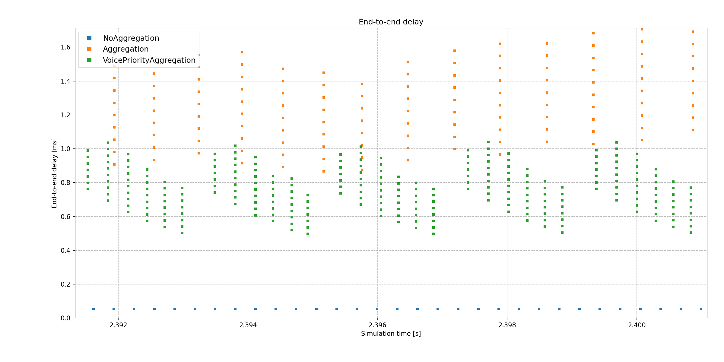
Here is the end-to-end delay of received packets in host2’s UDP app:
Without aggregation, delay is the lowest, because the packets don’t wait in the queue as much to be part of an aggregate frame. With the best effort priority aggregation, the delay is higher. The multiple data points above each other signify the reception of an aggregate frame, as the packets making up the aggregate frame are sent to the UDP app at the same time. The earliest packet in the aggregate frame has been in the transmission queue for the longest, so it has the most delay. In the voice priority aggregation case, the delay is lower, because the MAC waits less before acquiring the channel when sending the packets.
Note that the voice priority aggregate frames are spaced closer to each other horizontally than the best effort ones, because multiple aggregate frames are sent during a TXOP, and there is no contention between them. The vertical spacing of the data points in aggregate frames corresponds to the send interval of the UDP app.
Thus, aggregation actually increases delay while increasing throughput.
When aggregation is used, another column of aggregate frame data points could fit on the chart below the existing aggregate frame data points. This is because the MAC actually assembles an additional aggregate frame before sending the current one, thus increasing delay. This is an implementation detail.
Sources: omnetpp.ini, AggregationShowcase.ned
Try It Yourself
If you already have INET and OMNeT++ installed, start the IDE by typing
omnetpp, import the INET project into the IDE, then navigate to the
inet/showcases/wireless/aggregation folder in the Project Explorer. There, you can view
and edit the showcase files, run simulations, and analyze results.
Otherwise, there is an easy way to install INET and OMNeT++ using opp_env, and run the simulation interactively.
Ensure that opp_env is installed on your system, then execute:
$ opp_env run inet-4.0 --init -w inet-workspace --install --chdir \
   -c 'cd inet-4.0.*/showcases/wireless/aggregation && inet'
This command creates an inet-workspace directory, installs the appropriate
versions of INET and OMNeT++ within it, and launches the inet command in the
showcase directory for interactive simulation.
Alternatively, for a more hands-on experience, you can first set up the workspace and then open an interactive shell:
$ opp_env install --init -w inet-workspace inet-4.0
$ cd inet-workspace
$ opp_env shell
Inside the shell, start the IDE by typing omnetpp, import the INET project,
then start exploring.
