Step 9. Leaving some part of the network unconfigured
Goals
Configuring the whole network is not always desirable, because some parts of the network should rather be configured dynamically. In this step, some wired and wireless LANs’ addresses are left unspecified by the configurator, and they get addresses with DHCP.
The model
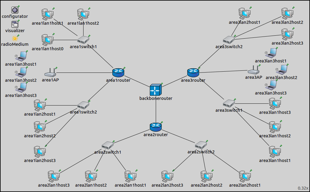
This step uses the ConfiguratorC network, defined in
ConfiguratorC.ned.
The configuration for this step in omnetpp.ini is the following:
[Config Step9]
sim-time-limit = 100s
network = ConfiguratorC
description = "Leaving some part of the network unconfigured"

# Configurator settings
*.configurator.config = xmldoc("step9.xml")

# SSID settings
*.area1AP.wlan[*].mgmt.ssid = "area1lan3"
*.area3AP.wlan[*].mgmt.ssid = "area3lan3"

*.area1lan3host*.wlan[*].agent.defaultSsid = "area1lan3"
*.area3lan3host*.wlan[*].agent.defaultSsid = "area3lan3"

# DHCP server in routers
*.area1router.hasDhcp = true
*.area1router.dhcp.numReservedAddresses = 2
*.area1router.dhcp.leaseTime = 100s
*.area1router.dhcp.maxNumClients = 3
*.area1router.dhcp.interface = "eth3"

*.area2router.hasDhcp = true
*.area2router.dhcp.numReservedAddresses = 2
*.area2router.dhcp.leaseTime = 100s
*.area2router.dhcp.maxNumClients = 3
*.area2router.dhcp.interface = "eth0"

*.area3router.hasDhcp = true
*.area3router.dhcp.numReservedAddresses = 2
*.area3router.dhcp.leaseTime = 100s
*.area3router.dhcp.maxNumClients = 3
*.area3router.dhcp.interface = "eth3"

# DHCP in hosts
*.area1lan3host1.numApps = 1
*.area1lan3host2.numApps = 2
*.area1lan3host3.numApps = 1

*.area1lan3*.app[0].typename = "DhcpClient"

*.area2lan1*.numApps = 1
*.area2lan1*.app[0].typename = "DhcpClient"

*.area3lan3*.numApps = 1
*.area3lan3*.app[*].typename = "DhcpClient"

# PingApp in host
*.area1lan3host2.app[1].typename = "PingApp"
*.area1lan3host2.app[1].destAddr = "area3lan3host2"
*.area1lan3host2.app[1].startTime = 3s
# TODO: should it be [0] or [*] ?
# Visualizer settings
*.visualizer.routingTableVisualizer.displayRoutingTables = true
*.visualizer.routingTableVisualizer.destinationFilter = "area3lan3host2"

**.forwarding = true

# Wireless settings
*.*.wlan[*].bitrate = 54Mbps
It boils down to the following:
Similarly to Step 8B, members of the two wireless LANs are specified by SSID.
Area1lan3host2is configured to pingarea3lan3host3. The ping application is delayed, so it starts sending pings after the hosts associated with the access points and got their addresses from the DHCP servers.DhcpServer submodules are added to the area routers. The DHCP server is configured to listen on the interface connecting to the unspecified LAN. The interface’s netmask is the DHCP server’s address range.
DhcpClient submodules are added to the LANs which are unspecified by the configurator. There is one such LAN in each area; they are
area1lan3,area2lan1andarea3lan3. Hosts in these LANs get the addresses from the DHCP server in the corresponding area router.Routes to
area3lan3host3are visualized.
The XML configuration in step9.xml is the following:
<config>
	<interface hosts="area1lan1*" address="10.1.1.x" netmask="255.255.255.x"/>
	<interface hosts="area1lan2*" address="10.1.2.x" netmask="255.255.255.x"/>
	<interface hosts="area2lan2*" address="10.2.2.x" netmask="255.255.255.x"/>
	<interface hosts="area3lan1*" address="10.3.1.x" netmask="255.255.255.x"/>
	<interface hosts="area3lan2*" address="10.3.2.x" netmask="255.255.255.x"/>
	<interface hosts="backbonerouter" towards="area1router" address="10.1.0.x" netmask="255.255.255.x"/>
	<interface hosts="backbonerouter" towards="area2router" address="10.2.0.x" netmask="255.255.255.x"/>
	<interface hosts="backbonerouter" towards="area3router" address="10.3.0.x" netmask="255.255.255.x"/>
	<interface hosts="area1router" names="eth3" address="10.1.3.1" netmask="255.255.255.x"/>
	<interface hosts="area2router" names="eth0" address="10.2.1.1" netmask="255.255.255.x"/>
	<interface hosts="area3router" names="eth3" address="10.3.3.1" netmask="255.255.255.x"/>
	<interface hosts="*router*" address="10.x.x.x" netmask="255.255.255.x"/>
</config>
Addresses are assigned hierarchically. Five LANs in the network have addresses assigned by the configurator. Three LANs get their addresses from DHCP servers, their interfaces are left unspecified by the configurator. This is accomplished by the lack of address assignment rules for these hosts in the XML configuration. The area routers’ interfaces connecting to the latter LANs need to be specified in order to have correct routes to these LANs. Additionally, the addresses for these interfaces need to be assigned specifically, and they have to fall in the configured DHCP server address ranges.
Results
The addresses and routes are visualized below. The state of the network at the start of the simulation is shown on the following image:
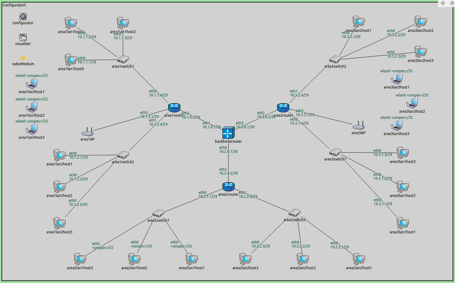
The hosts of area1lan3, area2lan1, and area3lan3 have
unspecified addresses. The routing tables of all hosts contain subnet
routes to these three LANs. Since these hosts don’t have addresses at
the start of the simulation, there are no routes leading to
area3lan3host2 that can be visualized.
Though the hosts in the three LANs have unspecified addresses, subnet
routes leading to these LANs are added to the routing tables of all
hosts. The addresses for the interfaces connecting to these LANs have a
netmask assigned, so there are addresses allocated for the unspecified
hosts. For example, area1router’s eth3 interface has the address
10.1.4.1/29 and has four addresses allocated (10.1.4.2..5).
The routing tables of area1lan3host2, area1router and
backbonerouter are the following (routes for reaching the
unspecified hosts are highlighted):
Node ConfiguratorC.area1lan3host2
-- Routing table --
Destination      Netmask          Gateway          Iface            Metric
10.1.3.0         255.255.255.248  *                wlan0 (unspec)        0
*                *                10.1.3.1         wlan0 (unspec)        0

Node ConfiguratorC.area1router
-- Routing table --
Destination      Netmask          Gateway          Iface            Metric
10.1.0.1         255.255.255.255  *                eth2 (10.1.0.2)       0
10.1.1.0         255.255.255.248  *                eth0 (10.1.1.4)       0
10.1.2.0         255.255.255.248  *                eth1 (10.1.2.4)       0
10.1.3.0         255.255.255.248  *                eth3 (10.1.3.1)       0
10.2.0.0         255.254.0.0      10.1.0.1         eth2 (10.1.0.2)       0

Node ConfiguratorC.backbonerouter
-- Routing table --
Destination      Netmask          Gateway          Iface            Metric
10.1.0.2         255.255.255.255  *                eth1 (10.1.0.1)       0
10.2.0.2         255.255.255.255  *                eth0 (10.2.0.1)       0
10.3.0.2         255.255.255.255  *                eth2 (10.3.0.1)       0
10.1.0.0         255.255.252.0    10.1.0.2         eth1 (10.1.0.1)       0
10.2.0.0         255.255.252.0    10.2.0.2         eth0 (10.2.0.1)       0
10.3.0.0         255.255.252.0    10.3.0.2         eth2 (10.3.0.1)       0
Note
area1lan3host2has a default route for reaching the other hosts in the LAN.area1Routerhas a route for reaching hosts inarea1lan3, and a default route for reaching area 2 and area 3.backbonerouterhas subnet routes to each area.
In the following video, area1lan3host2 sends a ping packet to
area3lan3host2:
No routes are visualized initially because area3lan3host2 (the
destination of route visualization) has an unspecified IP address. When
it gets an address from the DHCP server, the routes leading towards
area3lan3host2 appear.
Sources: omnetpp.ini,
ConfiguratorC.ned
Discussion
Use this page in the GitHub issue tracker for commenting on this tutorial.