Step 7. Configuring a hierarchical network
Goals
In complex hierarchical networks, routing tables can grow very large. This step demonstrates ways the configurator can reduce the size of routing tables by optimization and the use of hierarchically assigned addresses. The step contains three parts:
Part A: Automatically assigned addresses, no optimization
Part B: Automatically assigned addresses, using optimization
Part C: Hierarchically assigned addresses, using optimization
Part A - Automatically assigned addresses
Assigning addresses hierarchically in a network with hierarchical topology can reduce the size of routing tables. However, the configurator’s automatic address assignment with its default settings doesn’t assign addresses hierarchically. This part uses automatic address assignment, and the configurator’s routing table optimization features are turned off. The size of routing tables in this part can serve as a baseline to compare with.
Configuration
All three parts in this step use the ConfiguratorB network defined
in ConfiguratorB.ned. The network
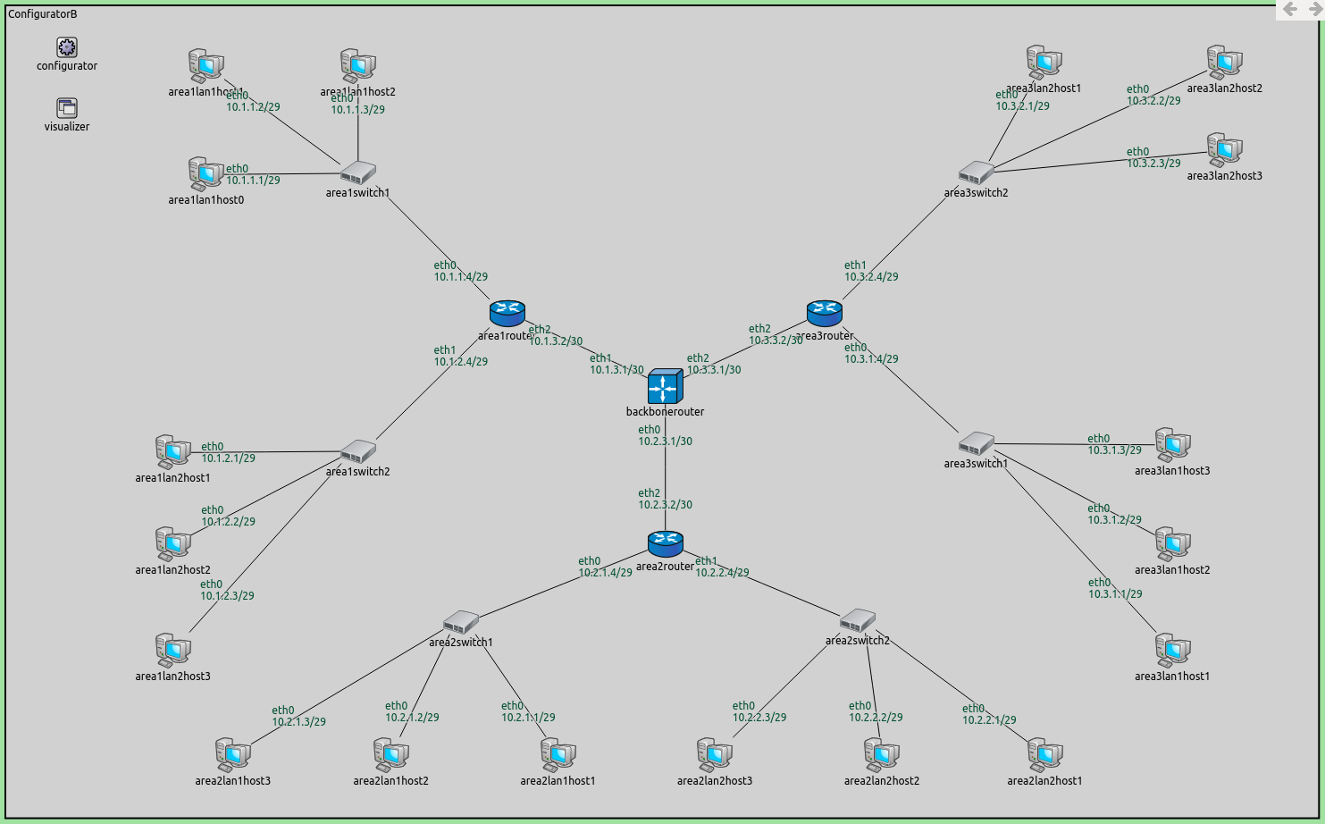
looks like this:
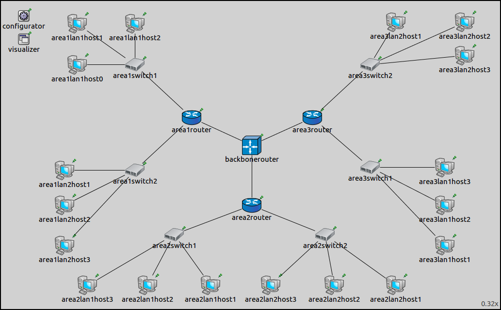
The network is comprised of three areas, each containing two local area networks (LANs). Each LAN contains three hosts. The hosts in the LAN connect to an area router through switches. The three area routers connect to a central backbone router. The network contains three hierarchical levels, which correspond to the hosts in the LANs, the area routers, and the backbone router.
The configuration for this part in omnetpp.ini is the following:
[Config Step7A]
sim-time-limit = 500s
network = ConfiguratorB
description = "Configuring a hierarchical network - A: non-optimized, fully automatic IP address assignment and static routes"

*.configurator.assignDisjunctSubnetAddresses = false
*.configurator.addDefaultRoutes = false
*.configurator.addSubnetRoutes = false
*.configurator.optimizeRoutes = false
This configuration turns off every kind of optimization relating to address assignment and route generation. This means that nodes will have an individual routing table entry to every destination interface.
Results
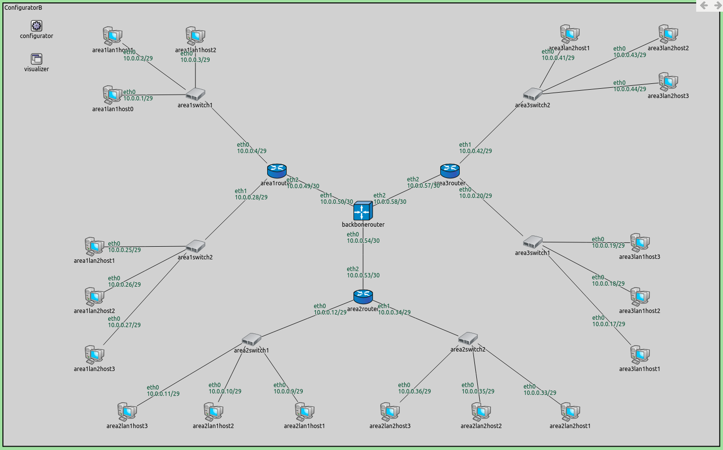
The assigned addresses are shown in the image below:
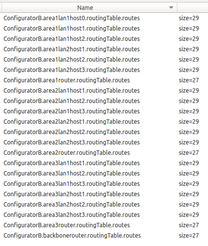
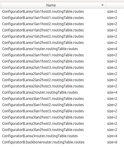
The size of some of the routing tables are the following:
The routing tables of a host (area1lan2host2) and a router
(area1router) are shown below. The backbonerouter’s routing
table is similar to area1router’s.
Node ConfiguratorB.area1lan2host2
-- Routing table --
Destination      Netmask          Gateway          Iface            Metric
10.0.0.1         255.255.255.255  10.0.0.28        eth0 (10.0.0.26)      0
10.0.0.2         255.255.255.255  10.0.0.28        eth0 (10.0.0.26)      0
10.0.0.3         255.255.255.255  10.0.0.28        eth0 (10.0.0.26)      0
10.0.0.4         255.255.255.255  10.0.0.28        eth0 (10.0.0.26)      0
10.0.0.9         255.255.255.255  10.0.0.28        eth0 (10.0.0.26)      0
10.0.0.10        255.255.255.255  10.0.0.28        eth0 (10.0.0.26)      0
10.0.0.11        255.255.255.255  10.0.0.28        eth0 (10.0.0.26)      0
10.0.0.12        255.255.255.255  10.0.0.28        eth0 (10.0.0.26)      0
10.0.0.17        255.255.255.255  10.0.0.28        eth0 (10.0.0.26)      0
10.0.0.18        255.255.255.255  10.0.0.28        eth0 (10.0.0.26)      0
10.0.0.19        255.255.255.255  10.0.0.28        eth0 (10.0.0.26)      0
10.0.0.20        255.255.255.255  10.0.0.28        eth0 (10.0.0.26)      0
10.0.0.25        255.255.255.255  *                eth0 (10.0.0.26)      0
10.0.0.27        255.255.255.255  *                eth0 (10.0.0.26)      0
10.0.0.28        255.255.255.255  *                eth0 (10.0.0.26)      0
10.0.0.33        255.255.255.255  10.0.0.28        eth0 (10.0.0.26)      0
10.0.0.34        255.255.255.255  10.0.0.28        eth0 (10.0.0.26)      0
10.0.0.35        255.255.255.255  10.0.0.28        eth0 (10.0.0.26)      0
10.0.0.36        255.255.255.255  10.0.0.28        eth0 (10.0.0.26)      0
10.0.0.41        255.255.255.255  10.0.0.28        eth0 (10.0.0.26)      0
10.0.0.42        255.255.255.255  10.0.0.28        eth0 (10.0.0.26)      0
10.0.0.43        255.255.255.255  10.0.0.28        eth0 (10.0.0.26)      0
10.0.0.44        255.255.255.255  10.0.0.28        eth0 (10.0.0.26)      0
10.0.0.49        255.255.255.255  10.0.0.28        eth0 (10.0.0.26)      0
10.0.0.50        255.255.255.255  10.0.0.28        eth0 (10.0.0.26)      0
10.0.0.53        255.255.255.255  10.0.0.28        eth0 (10.0.0.26)      0
10.0.0.54        255.255.255.255  10.0.0.28        eth0 (10.0.0.26)      0
10.0.0.57        255.255.255.255  10.0.0.28        eth0 (10.0.0.26)      0
10.0.0.58        255.255.255.255  10.0.0.28        eth0 (10.0.0.26)      0

Node ConfiguratorB.area1router
-- Routing table --
Destination      Netmask          Gateway          Iface            Metric
10.0.0.1         255.255.255.255  *                eth0 (10.0.0.4)       0
10.0.0.2         255.255.255.255  *                eth0 (10.0.0.4)       0
10.0.0.3         255.255.255.255  *                eth0 (10.0.0.4)       0
10.0.0.9         255.255.255.255  10.0.0.50        eth2 (10.0.0.49)      0
10.0.0.10        255.255.255.255  10.0.0.50        eth2 (10.0.0.49)      0
10.0.0.11        255.255.255.255  10.0.0.50        eth2 (10.0.0.49)      0
10.0.0.12        255.255.255.255  10.0.0.50        eth2 (10.0.0.49)      0
10.0.0.17        255.255.255.255  10.0.0.50        eth2 (10.0.0.49)      0
10.0.0.18        255.255.255.255  10.0.0.50        eth2 (10.0.0.49)      0
10.0.0.19        255.255.255.255  10.0.0.50        eth2 (10.0.0.49)      0
10.0.0.20        255.255.255.255  10.0.0.50        eth2 (10.0.0.49)      0
10.0.0.25        255.255.255.255  *                eth1 (10.0.0.28)      0
10.0.0.26        255.255.255.255  *                eth1 (10.0.0.28)      0
10.0.0.27        255.255.255.255  *                eth1 (10.0.0.28)      0
10.0.0.33        255.255.255.255  10.0.0.50        eth2 (10.0.0.49)      0
10.0.0.34        255.255.255.255  10.0.0.50        eth2 (10.0.0.49)      0
10.0.0.35        255.255.255.255  10.0.0.50        eth2 (10.0.0.49)      0
10.0.0.36        255.255.255.255  10.0.0.50        eth2 (10.0.0.49)      0
10.0.0.41        255.255.255.255  10.0.0.50        eth2 (10.0.0.49)      0
10.0.0.42        255.255.255.255  10.0.0.50        eth2 (10.0.0.49)      0
10.0.0.43        255.255.255.255  10.0.0.50        eth2 (10.0.0.49)      0
10.0.0.44        255.255.255.255  10.0.0.50        eth2 (10.0.0.49)      0
10.0.0.50        255.255.255.255  *                eth2 (10.0.0.49)      0
10.0.0.53        255.255.255.255  10.0.0.50        eth2 (10.0.0.49)      0
10.0.0.54        255.255.255.255  10.0.0.50        eth2 (10.0.0.49)      0
10.0.0.57        255.255.255.255  10.0.0.50        eth2 (10.0.0.49)      0
10.0.0.58        255.255.255.255  10.0.0.50        eth2 (10.0.0.49)      0
There are 30 interfaces in the network (18 hosts * 1 interface + 4
routers * 3 interfaces). All routing table entries have
255.255.255.255 netmasks, i.e. separate routes to all destination
interfaces. Thus, hosts have 29 entries in their routing tables, for the
29 other interfaces. Similarly, routers have 27 entries.
Part B - Automatically assigned addresses, using optimization
In this part, we turn on the optimization features of the configurator that were turned off in Part A. This should optimize routing tables and decrease table size.
Configuration
The configuration for this part in omnetpp.ini is the following:
[Config Step7B]
sim-time-limit = 500s
network = ConfiguratorB
description = "Configuring a hierarchical network - B: optimized, fully automatic IP address assignment and static routes"
The configuration is empty, the default NED parameter values take
effect. That means that the following optimization features are turned
on: assignDisjunctSubnetAddresses, addDefaultRoutes,
addSubnetRoutes, optimizeRoutes.
Results
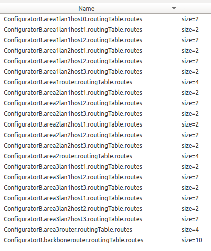
The addresses are the same, but the routing table sizes have gone down:
The routing tables of a host, an area router and the backbone router are the following:
Node ConfiguratorB.area1lan1host0
-- Routing table --
Destination      Netmask          Gateway          Iface            Metric
10.0.0.0         255.255.255.248  *                eth0 (10.0.0.1)       0
*                *                10.0.0.4         eth0 (10.0.0.1)       0

Node ConfiguratorB.area1router
-- Routing table --
Destination      Netmask          Gateway          Iface            Metric
10.0.0.50        255.255.255.255  *                eth2 (10.0.0.49)      0
10.0.0.0         255.255.255.248  *                eth0 (10.0.0.4)   0
10.0.0.24        255.255.255.248  *                eth1 (10.0.0.28)      0
10.0.0.0         255.255.255.192  10.0.0.50        eth2 (10.0.0.49)      0

Node ConfiguratorB.backbonerouter
-- Routing table --
Destination      Netmask          Gateway          Iface            Metric
10.0.0.49        255.255.255.255  *                eth0 (10.0.0.50)      0
10.0.0.53        255.255.255.255  *                eth2 (10.0.0.54)      0
10.0.0.57        255.255.255.255  *                eth1 (10.0.0.58)      0
10.0.0.8         255.255.255.248  10.0.0.53        eth2 (10.0.0.54)      0
10.0.0.16        255.255.255.248  10.0.0.57        eth1 (10.0.0.58)      0
10.0.0.32        255.255.255.248  10.0.0.53        eth2 (10.0.0.54)      0
10.0.0.40        255.255.255.248  10.0.0.57        eth1 (10.0.0.58)      0
10.0.0.0         255.255.255.224  10.0.0.49        eth0 (10.0.0.50)      0
10.0.0.0         255.255.255.192  10.0.0.53        eth2 (10.0.0.54)      0
10.0.0.0         255.255.255.192  10.0.0.57        eth1 (10.0.0.58)      0
We can make the following observations:
Hosts have just two routing table entries. One for reaching other hosts in their LANs, and a default route.
The area routers have a rule for reaching the backbone router, two rules for reaching the two LANs they’re connected to, and a default rule for reaching the rest of the network through the backbone router.
Similarly, the backbone router has three rules for reaching the three area routers, and six rules for reaching the six LANs in the network.
The backbone router has separate rules for the two LANs connected to an area router because the addresses are not contiguously assigned to the two LANs (e.g.
area2lan1has address 10.0.0.8/29,area2lan2has 10.0.0.32/29. Butarea3lan1has 10.0.0.16/29, which is between the two former address ranges). Thus, area 2 cannot be covered by a single rule.
Part C - Hierarchically assigned addresses, optimized routing tables
Having hierarchically assigned addresses in a network results in smaller routing table sizes, because a large distant network can be covered with just one rule in a core router’s routing table.
Configuration
The configuration for this part in omnetpp.ini is the following:
[Config Step7C]
sim-time-limit = 500s
network = ConfiguratorB
description = "Configuring a hierarchical network - C: optimized, hierarchically assigned IP addresses and static routes"

*.configurator.config = xmldoc("step7c.xml")
As in the previous part, all of the configurator’s routing table optimization features are enabled. The XML configuration for this part in step7c.xml is the following:
<config>
	<interface hosts="area1lan1*" address="10.1.1.x" netmask="255.255.255.x"/>
	<interface hosts="area1lan2*" address="10.1.2.x" netmask="255.255.255.x"/>
	<interface hosts="area2lan1*" address="10.2.1.x" netmask="255.255.255.x"/>
	<interface hosts="area2lan2*" address="10.2.2.x" netmask="255.255.255.x"/>
	<interface hosts="area3lan1*" address="10.3.1.x" netmask="255.255.255.x"/>
	<interface hosts="area3lan2*" address="10.3.2.x" netmask="255.255.255.x"/>
	<interface hosts="backbonerouter" towards="area1*" address="10.1.3.x" netmask="255.255.255.x"/>
	<interface hosts="backbonerouter" towards="area2*" address="10.2.3.x" netmask="255.255.255.x"/>
	<interface hosts="backbonerouter" towards="area3*" address="10.3.3.x" netmask="255.255.255.x"/>
	<interface hosts="*" address="10.x.x.x" netmask="255.255.255.x"/>
</config>
This XML configuration assigns addresses hierarchically in the following
way, when looking down the hierarchy from the backbone router towards
the hosts: - The first octet of the address for all nodes is 10, i.e.
10.x.x.x - The second octet denotes the area, e.g. 10.2.x.x
corresponds to area 2 - The third octet denotes the LAN within the area,
e.g. 10.2.1.x corresponds to lan1 in area 2 - The forth octet is
the host identifier within a LAN, e.g. 10.2.1.4 corresponds to
host4 in lan1 in area 2
With this setup, it is possible to cover an area with just one rule in the routing table of the backbone router. Similarly, the area routers need two rules for each LAN that they are connected to.
Results
The image below shows the assigned addresses.
The sizes of some of the routing tables are displayed on the following image.
The routing tables are the following:
Node ConfiguratorB.area1lan1host0
-- Routing table --
Destination      Netmask          Gateway          Iface           Metric
10.1.1.0         255.255.255.248  *                eth0 (10.1.1.1)      0
*                *                10.1.1.4         eth0 (10.1.1.1)      0

Node ConfiguratorB.area1router
-- Routing table --
Destination      Netmask          Gateway          Iface           Metric
10.1.3.1         255.255.255.255  *                eth2 (10.1.3.2)      0
10.1.1.0         255.255.255.248  *                eth0 (10.1.1.4)      0
10.1.2.0         255.255.255.248  *                eth1 (10.1.2.4)      0
10.2.0.0         255.254.0.0      10.1.3.1         eth2 (10.1.3.2)      0

Node ConfiguratorB.backbonerouter
-- Routing table --
Destination      Netmask          Gateway          Iface           Metric
10.1.3.2         255.255.255.255  *                eth0 (10.1.3.1)      0
10.2.3.2         255.255.255.255  *                eth2 (10.2.3.1)      0
10.3.3.2         255.255.255.255  *                eth1 (10.3.3.1)      0
10.1.0.0         255.255.252.0    10.1.3.2         eth0 (10.1.3.1)      0
10.2.0.0         255.255.252.0    10.2.3.2         eth2 (10.2.3.1)      0
10.3.0.0         255.255.252.0    10.3.3.2         eth1 (10.3.3.1)      0
Note the following:
Hosts’ routing tables contain just two rules, as in the previous part. One is for reaching the other members of the host’s LAN, and a default rule for reaching everything else through the area’s router.
The area routers’ routing tables contain a specific rule for reaching the backbone router, two rules for reaching the two LANs that belong to the router’s area, and a default rule for reaching everything else through the backbone router.
The backbone router’s routing table contains three specific rules for reaching the three area routers, and three rules to reach the three areas.
The difference between the configuration for this part and the previous one is that addresses are assigned hierarchically in this part. The routing table of the backbone router contains six entries instead of 10 in the previous part. The other nodes’ routing tables remained the same. The difference is not drastic because the network is small. However, using hierarchical address assignment in a larger network would make a significant difference in routing table size.
Sources: omnetpp.ini,
ConfiguratorB.ned
Discussion
Use this page in the GitHub issue tracker for commenting on this tutorial.