Step 4. Setting up static routing
Goals
In this step, we set up routing so that packets can flow from host A to B. For this to happen, the intermediate nodes will need to act as routers. As we still want to keep things simple, we’ll use statically added routes that remain unchanged throughout the simulation.
We also configure visualization so that we can see the paths packets take when traveling from host A to B.
The model
Setting up routing
For the recently added hosts to act as routers, IPv4 forwarding needs to
be enabled. This can be done by setting the forwarding parameter of
StandardHost.
We also need to set up static routing. Static configuration in the INET
Framework is often done by configurator modules. Static IPv4
configuration, including address assignment and adding routes, is
usually done using the Ipv4NetworkConfigurator module. The model
already has an instance of this module, the configurator submodule.
The configurator can be configured using an XML specification and some
additional parameters. Here, the XML specification is provided as a
string constant inside the ini file.
Without going into details about the contents of the XML configuration string and other configurator parameters, we tell the configurator to assign IP addresses in the 10.0.0.x range, and to create routes based on the estimated packet error rate of links between the nodes. (The configurator looks at the wireless network as a full graph. Links with high error rates will have high costs, and links with low error rates will have low costs. Routes are formed such as to minimize their costs. In the case of the GenericUnitDiskRadio model, the error rate is 1 for nodes that are out of range and a very small value for ones in range. The result will be that nodes that are out of range of each other will send packets to intermediate nodes that can forward them.)
Visualization
The IntegratedCanvasVisualizer we use as the visualizer
submodule in this network contains a networkRouteVisualizer module,
which is able to render packet paths. This module displays paths where a
packet has been recently sent between the network layers of the two end
hosts. The path is displayed as a colored arrow that goes through the
visited hosts. The path continually fades, and then it disappears after a
certain amount of time unless it is reinforced by another packet.
The network route visualizer is activated by setting its
displayRoutes parameter to true. Its packetFilter parameter
specifies which packets it should take into account. By default, it is
set to *, which means all packets. Our UDP application generates
packets with the name UDPData-0, UDPData-1, etc, so we set the
packet filter to UDPData* in order to filter out other types of
packets that will appear in later steps.
Configuration:
[Config Wireless04]
description = Setting up static routing
extends = Wireless03

*.host*.forwarding = true

*.configurator.config = xml("<config><interface hosts='**' address='10.0.0.x' netmask='255.255.255.0'/><autoroute metric='errorRate'/></config>")
*.configurator.optimizeRoutes = false
*.host*.ipv4.routingTable.netmaskRoutes = ""

*.visualizer.physicalLinkVisualizer.displayLinks = true
*.visualizer.dataLinkVisualizer.displayLinks = true
*.visualizer.networkRouteVisualizer.displayRoutes = true
*.visualizer.*LinkVisualizer.lineShift = 0
*.visualizer.networkRouteVisualizer.lineShift = 0
*.visualizer.networkRouteVisualizer.packetFilter = "UDPData*"
Results
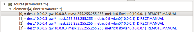
Routing tables are stored in the routingTable submodules of hosts,
and can be inspected in the runtime GUI. The routing table of host A
(10.0.0.1) can be seen in the following image. It tells that host B
(10.0.0.2) can be reached via host R1 (10.0.0.3), as specified by the
gateway (gw) value.
When the first packet sent by host A arrives at host R1, a dotted dark yellow arrow appears between the two hosts indicating a successful physical layer exchange, as it was noted earlier. A few events later but still at the same simulation time, a cyan-colored arrow appears on top of the dotted one. The cyan arrow represents a successful exchange between the two data link layers of the same hosts. As opposed to the previous step, this happens because according to the routing table of host A, a packet destined to host B, has to be sent to host R1 (the gateway). As the packet reaches the network layer of host R1, it is immediately routed according to the routing table of this host directly towards host B. So when the first packet arrives at host B, first a dotted arrow appears, then a cyan arrow appears on top of that, similarly to the host R1 case. Still at the same simulation time, the packet leaves the network layer of host B towards the UDP protocol component. At this moment a new polyline arrow appears between host A and host B going through host R1. This blue arrow represents the route the packet has taken from first entering the network layer at host A until it left the network layer at host B.
Note that there are dotted arrows leading to host R2 and R3 even though they don’t transmit. This is because they receive the transmissions at the physical layer, but they discard the packets at the link layer because it is not addressed to them.
Note that the number of packets received by host B has dropped to about half of what we saw in step 2. This is so because R1’s NIC operates in half-duplex mode (it can only transmit or receive at any time, but not both), so it can only relay packets at half the rate that host A emits.
Number of packets received by host B: 1125
Sources: omnetpp.ini,
WirelessB.ned
Discussion
Use this page in the GitHub issue tracker for commenting on this tutorial.