IEEE 802.15.4 Smart Home
Goals
IEEE 802.15.4 is a widely used standard for wireless communication in sensor networks, which supports multiple options for the physical and MAC layers. This showcase demonstrates the narrowband IEEE 802.15.4 model available in INET. It contains an example simulation that features a wireless sensor network.
4.6The model
IEEE 802.15.4 is a standard that defines the physical layer and media access control (MAC) layer of low-rate wireless personal area networks (LR-WPANs). LR-WPANs are low power, low throughput communication networks, which can be used for creating wireless sensor networks (WSNs), Internet-of-things applications, etc. It defines multiple physical layer specifications (PHYs), based on different modulations, such as Direct Sequence Spread Spectrum (DSSS), Chirp Spread Spectrum (CSS), and Ultra-wideband (UWB). It also defines CSMA-CA and ALOHA MAC-layer protocols.
The INET implementation
INET features a narrowband and an ultra-wideband IEEE 802.15.4 PHY model:
This showcase demonstrates the narrowband model, Ieee802154NarrowbandRadio. It simulates a PHY that uses DSSS-OQPSK modulation and operates at 2.45 GHz. By default, signals are transmitted with a bandwidth of 2.8 MHz using 2.24 mW transmission power. The model is configured to use the scalar analog model.
The Ieee802154NarrowbandInterface module contains an
Ieee802154NarrowbandRadio and the corresponding
Ieee802154NarrowbandMac. The radio medium module required by
the radio is Ieee802154NarrowbandScalarRadioMedium. The analog model type is set
to scalar in both the radios and the radio medium by default. The radio
has default values for its parameters, based on the 802.15.4 standard.
For example, by default, it uses the carrier frequency of 2450 MHz, 2.8
MHz bandwidth, 250 kbps bitrate, and 2.24 mW transmission power. As
such, it works “out-of-the-box”, without setting any of its parameters.
The radio medium uses BreakpointPathLoss by default as its path loss
model. (Refer to the documentation to see all parameters and default values.)
The configuration
The showcase contains an example simulation, which demonstrates the operation of INET’s narrowband IEEE 802.15.4 model. The scenario is that wireless nodes are used to control lighting in an apartment. There are sensor nodes in the rooms working as presence sensors, detecting when people are in a room. They periodically send sensor data to a controller node, which decides how to adjust the lighting conditions in different rooms. The controller sends control packets to the lamps in the rooms to set their brightness or turn them on and off. All nodes use the IEEE 802.15.4 narrowband model to communicate. Note that this is not a working simulation of the light control and presence detection, just a mockup based on that scenario - only the periodic communication of the nodes is simulated.
The simulation can be run by choosing the Ieee802154 configuration
from omnetpp.ini. It uses the following network:
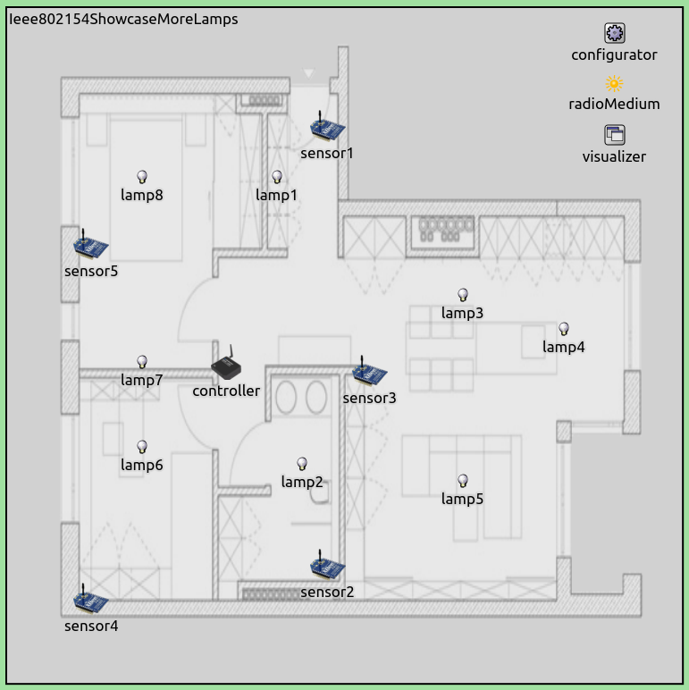
The network contains 14 hosts of the SensorNode type, which has an Ieee802154NarrowbandInterface by default. The network also contains an Ipv4NetworkConfigurator, an Ieee802154NarrowbandScalarRadioMedium, and an IntegratedCanvasVisualizer module.
Routes are set up according to a star topology, with the controller at
the center. This setup is achieved with the following configuration of
Ipv4NetworkConfigurator defined in the startopology.xml file:
<config>
	<interface hosts="controller" address="10.0.0.1" netmask="255.255.x.x"/>
	<interface hosts="**" address="10.0.x.x" netmask="255.255.x.x"/>
	<route hosts="controller" interface="wlan0" destination="*" gateway="*"/>
	<route hosts="lamp* sensor*" destination="*" gateway="10.0.0.1"/>
</config>
The following image shows the routes:
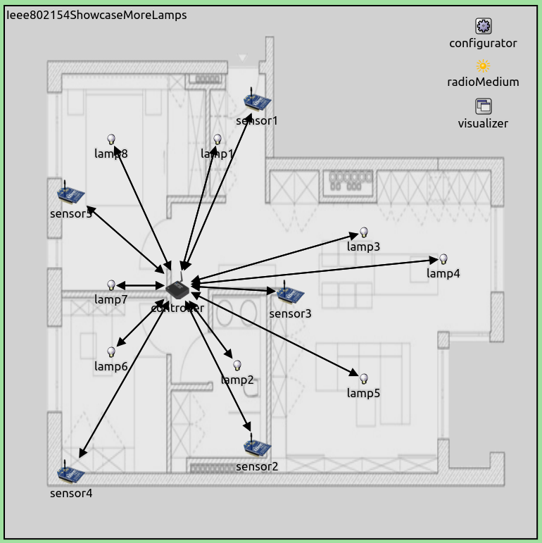
All sensors will send packets to the controller, and the controller will send packets to the lamps.
Here is the app configuration:
*.sensor*.numApps = 1
*.sensor*.app[*].typename = "UdpBasicApp"
*.sensor*.app[*].destAddresses = "controller"
*.sensor*.app[*].destPort = 1000
*.sensor*.app[*].sendInterval = 1s
*.sensor*.app[*].startTime = uniform(0s,1s)
*.sensor*.app[*].messageLength = 10Byte
*.sensor*.app[*].packetName = "SensorData"

*.controller.numApps = 2
*.controller.app[0].typename = "UdpBasicApp"
*.controller.app[0].destAddresses = "lamp1 lamp2 lamp3 lamp4 lamp5 lamp6 lamp7 lamp8"
*.controller.app[0].destPort = 1000
*.controller.app[0].sendInterval = 0.125s
*.controller.app[0].startTime = exponential(1s)
*.controller.app[0].messageLength = 10Byte
*.controller.app[0].packetName = "ControlData"

*.controller.app[1].typename = "UdpSink"
*.controller.app[1].localPort = 1000

*.lamp*.numApps = 1
*.lamp*.app[0].typename = "UdpSink"
*.lamp*.app[0].localPort = 1000
All sensors will send one 10-byte UDP packet to the controller each
second, with randomized start times. The controller will send one
10-byte UDP packet per second as well. The controller’s app is an
UdpBasicApp, and all lamp nodes are specified in its destination
parameter (a random destination is chosen for each packet.)
The radio’s parameters are not set; the default values will be used. We arbitrarily set the background noise power to -110 dBm.
Results
The following video shows the running simulation:
Sensors send packets to the controller, each sensor sending one packet per second. The controller sends 8 packets per second, to one of the lamps selected randomly. Note that each packet transmission is followed by an IEEE 802.15.4 ACK, but the ACKs are not visualized.
The SensorNode host type has energy storage and consumption modules
by default, so power consumption can be measured without adding any
modules to the hosts. SensorNode contains an
IdealEpEnergyStorage by default, and the radio in SensorNode
contains a SensorStateBasedEpEnergyConsumer. The
residualEnergyCapacity statistic is available.
We want to measure the energy consumption of the different nodes in the
network. For this, we use the Ieee802154Power configuration in
omnetpp.ini. This configuration extends the
Ieee802154 configuration with a simulation time limit of 100s,
and add the last to the result recording modes of residualEnergyCapacity
to plot its last recorded value at the end of the simulation:
[Config Ieee802154Power]
extends = Ieee802154
sim-time-limit = 100s

**.energyStorage.residualEnergyCapacity.result-recording-modes = +last
We plotted the energy consumption (-1 * residualEnergyCapacity) of
all nodes on the following bar chart (values in Joules):
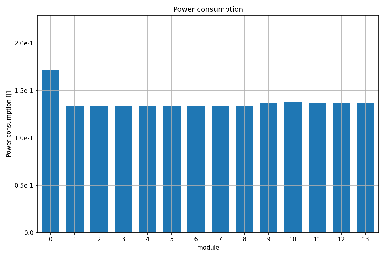
The sensors consumed a bit more power than the lamps, and the controller consumed the most energy. Nodes in the same role (i.e. lamps, sensors) consumed roughly the same amount of energy. Although the controller transmitted eight times as much as the sensors, it consumed just about 25% more energy. This is because energy consumption was dominated by the idle radio state. The controller transmitted in about 8% of the time, the sensors about 1%. Also, all transmissions were received by all nodes in the network at the PHY level, thus they shared the energy consumption due to reception. The small difference between the energy consumption of the lamps and the sensors is because the sensors transmitted data, and the lamps just transmitted ACKs (the data transmissions were longer than ACK transmissions, 1.7 ms vs 0.3 ms.)
Sources: omnetpp.ini, Ieee802154Showcase.ned
Try It Yourself
If you already have INET and OMNeT++ installed, start the IDE by typing
omnetpp, import the INET project into the IDE, then navigate to the
inet/showcases/wireless/ieee802154 folder in the Project Explorer. There, you can view
and edit the showcase files, run simulations, and analyze results.
Otherwise, there is an easy way to install INET and OMNeT++ using opp_env, and run the simulation interactively.
Ensure that opp_env is installed on your system, then execute:
$ opp_env run inet-4.6 --init -w inet-workspace --install --build-modes=release --chdir \
   -c 'cd inet-4.6.*/showcases/wireless/ieee802154 && inet'
This command creates an inet-workspace directory, installs the appropriate
versions of INET and OMNeT++ within it, and launches the inet command in the
showcase directory for interactive simulation.
Alternatively, for a more hands-on experience, you can first set up the workspace and then open an interactive shell:
$ opp_env install --init -w inet-workspace --build-modes=release inet-4.6
$ cd inet-workspace
$ opp_env shell
Inside the shell, start the IDE by typing omnetpp, import the INET project,
then start exploring.
Discussion
Use this page in the GitHub issue tracker for commenting on this showcase.