Step 6. Setting different metric for automatic routing table configuration
Goals
When setting up routes, the configurator uses the shortest path algorithm. By default, paths are optimized for hop count. However, there are other cost functions available, like data rate, error rate, etc. This step consists of two parts:
Part A demonstrates using the data rate metric for automatically setting up routes.
Part B demonstrates instructing the configurator not to use a link when setting up routes, by manually specifying a high link cost.
Part A: Using the data rate metric
When setting up routes, the configurator first builds a graph representing the network topology. A vertex in the graph represents a network node along with all of its interfaces. An edge represents a wired or wireless connection between two network interfaces. When building the network topology, wireless nodes are considered to be connected to all other wireless nodes in the same wireless network.
After the graph is built, the configurator assigns weights to vertices and edges according to the configured metric. Vertices that represent network nodes with IP forwarding turned off have infinite weight; all others have 0. Finally, the shortest path algorithm is used to determine the routes based on the assigned weights.
The available metrics are the following:
hopCount: routes are optimized for hop count. All edges have a cost of 1. This is the default metric.dataRate: routes prefer connections with higher bandwidth. Edge costs are inversely proportional to the data rate of the connection.delay: routes are optimized for lower delay. Edge costs are proportional to the delay of the connection.errorRate: routes are optimized for smaller error rate. Edge costs are proportional to the error rate of the connection. This is mostly useful for wireless networks because the error rate of wired connections is usually negligible.
Configuration
The configuration for this step extends Step 4, thus, it uses the ConfiguratorA network. The configuration in omnetpp.ini is the following:
[Config Step6A]
sim-time-limit = 500s
extends = Step4
description = "Setting different metric for automatic routing table configuration - using dataRate metric"

*.configurator.config = xmldoc("step6a.xml")

*.visualizer.routingTableVisualizer.destinationFilter = "host1"
Below is the XML configuration in step6a.xml:
<config>
	<interface hosts='**' address='10.x.x.x' netmask='255.x.x.x'/>
	<autoroute sourceHosts='**' metric='dataRate'/>
</config>
The XML configuration contains the default rule for IP address
assignment, and an <autoroute> element that configures the metric to
be used. The <autoroute> element specifies parameters for automatic
static routing table configuration. If no <autoroute> element is
specified, the configurator assumes a default that affects all routing
tables in the network, and computes shortest paths to all interfaces
according to the hop count metric. The <autoroute> element can
contain the following attributes:
sourceHosts: Selector attribute that selects which hosts’ routing tables should be modified. The default value is"**".destinationInterfaces: Parameter attribute that selects destination interfaces for which the shortest paths will be calculated. The default value is"**".metric: Parameter attribute that sets the metric to be used when calculating shortest paths. The default value is"hopCount".
There are sub-elements available in <autoroute>, which will be
discussed in Part B.
Here the <autoroute> element specifies that routes should be added
to the routing table of each host and the metric should be dataRate.
The configurator assigns weights to the graph’s edges that are inversely
proportional to the data rate of the network links. This way route
generation will favor routes with higher data rates.
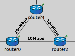
Note that router0 and router2 are connected with a 10 Mbit/s
ethernet cable, while router1 connects to the other routers with 100
Mbit/s ethernet cables. Since routes are optimized for data rate,
packets from router0 to router2 will go via router1 because
this path has higher bandwidth.
Results
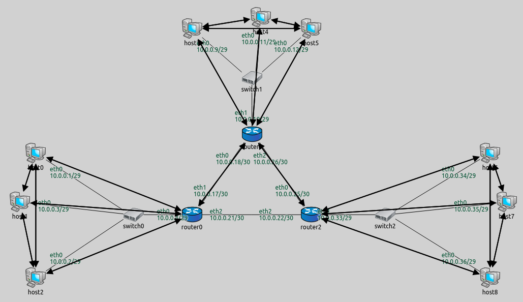
The following image shows the backward routes towards host1. The
resulting routes are similar to the ones in Step 5B. The difference is
that routes going backward, from hosts 6–8 to hosts 0–2, go through
router1. No traffic is routed between router0 and router2 at
all (as opposed to Step 4 and 5.)

The routing table of router0 is as follows:
Node ConfiguratorA.router0
-- Routing table --
Destination      Netmask          Gateway          Iface            Metric
10.0.0.18        255.255.255.255  *                eth1 (10.0.0.17)      0
10.0.0.0         255.255.255.248  *                eth0 (10.0.0.4)       0
10.0.0.0         255.255.255.192  10.0.0.18        eth1 (10.0.0.17)      0
The first two rules describe reaching router1 and hosts 0–2
directly. The last rule specifies that traffic to any other destination
should be routed towards router1.
The routing table of router2 is similar:
Node ConfiguratorA.router2
-- Routing table --
Destination      Netmask          Gateway          Iface            Metric
10.0.0.26        255.255.255.255  *                eth0 (10.0.0.25)      0
10.0.0.32        255.255.255.248  *                eth1 (10.0.0.33)      0
10.0.0.0         255.255.255.224  10.0.0.26        eth0 (10.0.0.25)      0
The following video shows host1 pinging host7 and host0
pinging host6. Routes towards host1 are visualized. The packets
don’t use the link between router0 and router2.
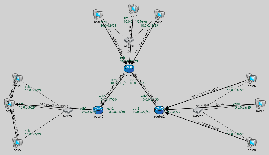
One can easily check that no routes go through the link between
router0 and router2 by setting the destination filter to "*"
in the visualizer. This indicates all routes in the network:
Part B - Manually specifying link cost
This part configures the same routes as Part A, where routes between
router0 and router2 lead through router1.
The configurator is instructed not to use the link between router0
and router2 when setting up routes, by specifying the cost of the
link to be infinite.
Configuration
The configuration for this step in omnetpp.ini is the following:
[Config Step6B]
sim-time-limit = 500s
extends = Step4
description = "Setting different metric for automatic routing table configuration - manually specifying link cost"

*.configurator.config = xmldoc("step6b.xml")

*.visualizer.routingTableVisualizer.destinationFilter = "host1"
The XML configuration in step6b.xml is as follows:
<config>
	<interface hosts='**' address='10.x.x.x' netmask='255.x.x.x'/>
	<autoroute metric='hopCount'>
		<link interfaces='*.router0.eth2' cost='infinite'/>
 	</autoroute>
</config>
The <autoroute> elements can also contain the following optional
sub-elements, which can be used to specify costs in the graph:
<node>: Specifies cost parameters to network nodes. Thehostsselector attribute selects which hosts are affected, and thecostparameter sets their costs. Both attributes are mandatory.<link>: Specifies cost parameters to network links. Theinterfacesselector attribute selects which links are affected, by specifying an interface they belong to. Thecostparameter sets the cost. Both attributes are mandatory.
This XML configuration specifies the metric to be hop count and sets
the cost of router0’s eth2 interface to infinite. This affects the
link between router0 and router2 - no routes should go through
it.
Results
The routes towards host1 are visualized on the following image:
The routes are the same as in Part A, where the data rate metric was
used, and routes didn’t use the 10Mbps link between router0 and
router2. In this part, the link between router0 and router2
is “turned off” by specifying an infinite cost for it. The following
video shows host1 pinging host7. Routes towards host1 are
visualized. The ping packets take the diverted route in both directions:
Sources: omnetpp.ini,
ConfiguratorA.ned
Discussion
Use this page in the GitHub issue tracker for commenting on this tutorial.