Credit-Based Shaping
Goals
Credit-based shaping (CBS), as defined in the IEEE 802.1Qav standard, is a traffic shaping mechanism that regulates the transmission rate of Ethernet frames to smooth out traffic and reduce bursts.
In this showcase, we demonstrate the configuration and operation of credit-based shaping in INET with an example simulation.
4.6Credit-Based Shaping Overview
The Credit Based Shaping (CBS) is an algorithm designed for network traffic management. Its core function is to limit the bandwidth a Traffic Class queue can transmit, ensuring optimal bandwidth distribution. It helps smooth out bursts by delaying the transmission of successive frames. CBS helps in mitigating network congestion in bridges and enhancing overall network performance.
In CBS, each outgoing queue is associated with a credit counter. The credit counter accumulates credits when the queue is idle, and consumes credits when frames are transmitted. The rate at which credits are accumulated and consumed is configured using parameters such as the idle slope and send slope.
When the queue contains a packet to be transmitted, the credit counter is checked. If the credit counter is non-negative, the frame is transmitted immediately. If the credit counter is negative, the frame is held back until the credit counter becomes non-negative.
CBS Implementation in INET
In INET, the credit-based shaper is implemented by the Ieee8021qCreditBasedShaper simple module. This module acts as a packet gate, allowing packets to pass through only when it is open. It can be combined with a packet queue to implement the credit-based shaper algorithm.
The Ieee8021qCreditBasedShaper module has the following parameters:
idleSlope: Determines the outgoing data rate of the shaper, measured in bits per secondsendSlope: The consumption rate of credits during transmission, measured in bits per second (default: idleSlope - channel bitrate)transmitCreditLimit: credit limit above which the gate is open, measured in bits (default: 0)minCreditandmaxCredit: a minimum and maximum limit for credits, measured in bits (default: no limit)
The idleSlope parameter determines the data rate at which the traffic will be limited, as measured
in the Ethernet channel (thus including protocol overhead). Typically, this is the only parameter that needs to be set,
as the others have reasonable defaults.
The shaper allows packets to pass through when the number of credits is zero or more. When the number of credits is positive, the shaper accumulates a burst reserve. As defined in the standard, if there are no packets in the queue, the credits are set to zero.
To conveniently incorporate a credit-based shaper into a network interface, it
can be added as a submodule to an Ieee8021qTimeAwareShaper. The
Ieee8021qTimeAwareShaper module supports a configurable number of traffic
classes, pre-existing queues for each class, and can be enabled for Ethernet
interfaces by setting the hasEgressTrafficShaping parameter in the
network node to true. To utilize a credit-based shaper, the
transmissionSelectionAlgorithm submodule of the time-aware shaper can be
overridden accordingly. As an example, here is a time-aware shaper module that
incorporates credit-based shaper submodules and supports two traffic classes:
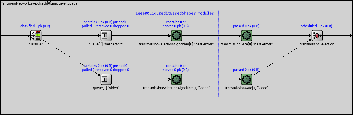
Packets entering the time-aware shaper module are classified into different traffic categories based on their PCP number using the PcpTrafficClassClassifier. The priority assignment is determined by the transmissionSelection submodule, which utilizes a PriorityScheduler configured to operate in reverse order, i.e. priority increases with the traffic class index. For example, in the provided image, video traffic takes precedence over best effort traffic.
The Model
The Network
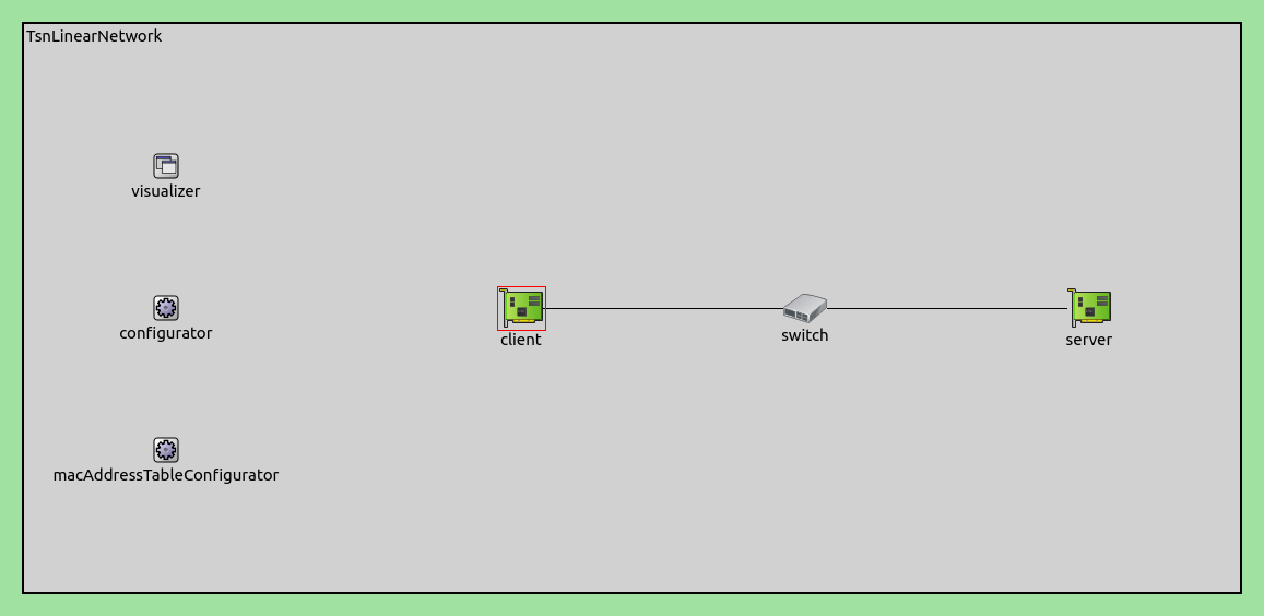
We demonstrate the operation of CBS using a network containing a client, a server, and a switch. The client and the server (TsnDevice) are connected through the switch (TsnSwitch), with 100Mbps Ethernet links:
Traffic
In this simulation, we configure the client to generate two streams of
fluctuating traffic, which are assigned to two traffic categories. We insert
credit-based shapers for each category into the switch’s outgoing interface
(eth1) to smooth traffic.
Analogous to the Time-Aware Shaping showcase, our objective is to isolate and observe the impact of the credit-based shaper on network traffic. To this end, we aim for the traffic to be only modified significantly by the credit-based shaper, avoiding any unintended traffic shaping effects elsewhere in the network. To achieve this, we set up two traffic source applications in the client, creating two separate data streams whose throughput varies sinusoidally with maximum values of ~47 Mbps and ~34 Mbps, respectively. Given these values, the network links are not operating at their full capacity, thereby eliminating any significant traffic shaping effects resulting from link saturation. Subsequently, we configure the traffic shaper to cap the data rates of these streams at ~42 Mbps and ~21 Mbps, respectively. As a result, the average incoming data rate is lower than the outgoing limit. Below are the details of the traffic configuration:
# client applications
*.client.numApps = 2
*.client.app[*].typename = "UdpSourceApp"
*.client.app[0].display-name = "best effort"
*.client.app[1].display-name = "video"
*.client.app[*].io.destAddress = "server"
*.client.app[0].io.destPort = 1000
*.client.app[1].io.destPort = 1001
*.client.app[*].source.packetLength = 1000B
*.client.app[0].source.productionInterval = replaceUnit(1 / (sin(dropUnit(simTime()) * 3) + 4.5), "ms")
*.client.app[1].source.productionInterval = replaceUnit(1 / (sin(dropUnit(simTime() * 1)) + sin(dropUnit(simTime() * 8)) + 2), "ms")

# server applications
*.server.numApps = 2
*.server.app[*].typename = "UdpSinkApp"
*.server.app[0].display-name = "best effort"
*.server.app[1].display-name = "video"
*.server.app[0].io.localPort = 1000
*.server.app[1].io.localPort = 1001
Traffic Shaping
Within the client, our goal is to classify packets originating from the two
packet sources into two traffic classes: best effort and
video. To achieve this, we activate IEEE 802.1 stream
identification and stream encoding functionalities by setting the
hasOutgoingStreams parameter in the client to true. We proceed by configuring the stream
identifier module within the bridging layer; this module is responsible for
associating outgoing packets with named streams based on their UDP destination
ports. Following this, the stream encoder sets the Priority Code Point (PCP) number on the packets according to
the assigned stream name (using the IEEE 802.1Q header’s PCP field):
# enable outgoing streams
*.client.hasOutgoingStreams = true

# client stream identification
*.client.bridging.streamIdentifier.identifier.mapping = [{stream: "best effort", packetFilter: expr(udp.destPort == 1000)},
                                                         {stream: "video", packetFilter: expr(udp.destPort == 1001)}]

# client stream encoding
*.client.bridging.streamCoder.encoder.mapping = [{stream: "best effort", pcp: 0},
                                                 {stream: "video", pcp: 4}]
We enable egress traffic shaping in the switch, which adds the time-aware shaper module to interfaces. In the time-aware shaper, we define two traffic classes, and configure the transmission selection algorithm submodules by setting their type to Ieee8021qCreditBasedShaper. This action adds two credit-based shaper modules, one for each traffic class. We then set the idle slope parameters of the two credit-based shapers to ~42 Mbps and ~21 Mbps, respectively:
# enable egress traffic shaping
*.switch.hasEgressTrafficShaping = true

# disable forwarding IEEE 802.1Q C-Tag
*.switch.bridging.directionReverser.reverser.excludeEncapsulationProtocols = ["ieee8021qctag"]

# credit based traffic shaping
*.switch.eth[1].macLayer.queue.numTrafficClasses = 2
*.switch.eth[1].macLayer.queue.*[0].display-name = "best effort"
*.switch.eth[1].macLayer.queue.*[1].display-name = "video"
*.switch.eth[1].macLayer.queue.transmissionSelectionAlgorithm[*].typename = "Ieee8021qCreditBasedShaper"
*.switch.eth[1].macLayer.queue.transmissionSelectionAlgorithm[0].idleSlope = 42.64Mbps # Channel data rate
*.switch.eth[1].macLayer.queue.transmissionSelectionAlgorithm[1].idleSlope = 21.32Mbps # Channel data rate
Note that we also disable forwarding of IEEE 802.1Q C-tags (VLAN tags), because we don’t need them after the switch. Otherwise the destination would drop all packets due to unknown protocol tag, because it’s missing the 8021q module.
Results
Let’s take a look at how the traffic changes in and between the various network nodes. First, we compare the data rate of the client application traffic with the shaper incoming traffic for the two traffic categories:
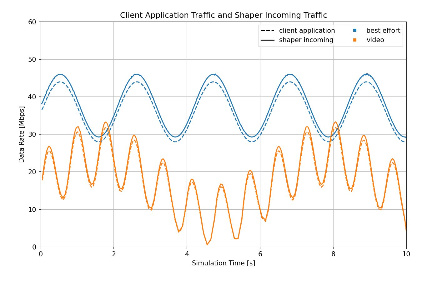
The client application and shaper incoming traffic are quite similar, but not identical. The shaper’s incoming traffic has a slightly higher data rate because of additional protocol overhead that wasn’t present in the application. Also, the two streams of packets are combined in the client’s network interface, which can cause some packets to be delayed. Therefore, even if we adjusted for the extra protocol overhead, the traffic wouldn’t match exactly.
Now let’s examine how the traffic changes in the shaper by comparing the data rate of the incoming and outgoing traffic:
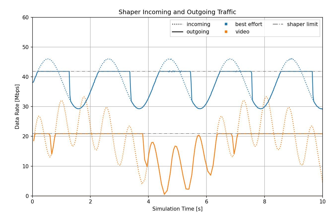
On average, the data rate of the incoming traffic is below the shaper’s limit, but there are intermittent periods when it exceeds the limit. When this happens, the shaper caps the data rate at the set limit, by storing packets temporarily and then sending them out eventually, which smooths out the outgoing traffic. When the data rate of the incoming traffic is below the shaper’s limit, traffic shaping isn’t needed, and the outgoing traffic mirrors the incoming traffic.
Note
The data rate specified in the ini file as the idle slope parameter corresponds to the channel data rate. However, the outgoing data rate inside the shaper differs slightly due to protocol overhead, including factors like the PHY (Physical Layer) and IFG (Interframe Gap). In this chart, we measure the data rate within the shaper, so we have displayed the data rate limits as calculated specifically for the shaper.
The next chart compares the shaper outgoing and server application traffic:
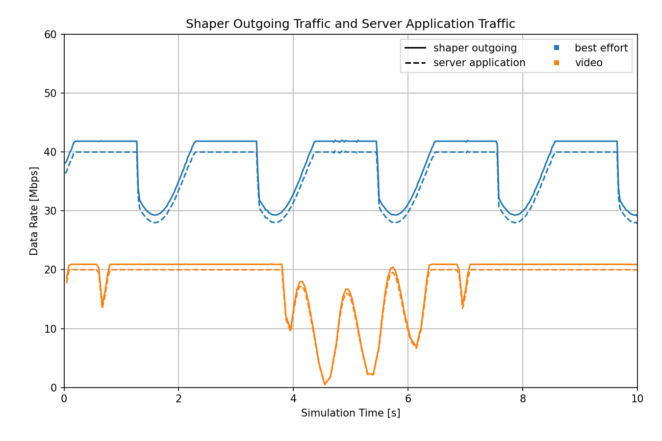
Much like the first chart, the shaper outgoing and server application traffic profiles are similar, but the shaper’s traffic is slightly higher due to protocol overhead.
Having examined the traffic across the entire network, we can conclude that the traffic undergoes significant changes mainly within the shaper, while other parts of the network remain unaffected by traffic shaping, consistent with our expectations.
The sequence chart below illustrates the transmission of frames within the network. In this chart, the best effort traffic category is represented in blue, while the video category is depicted in red.
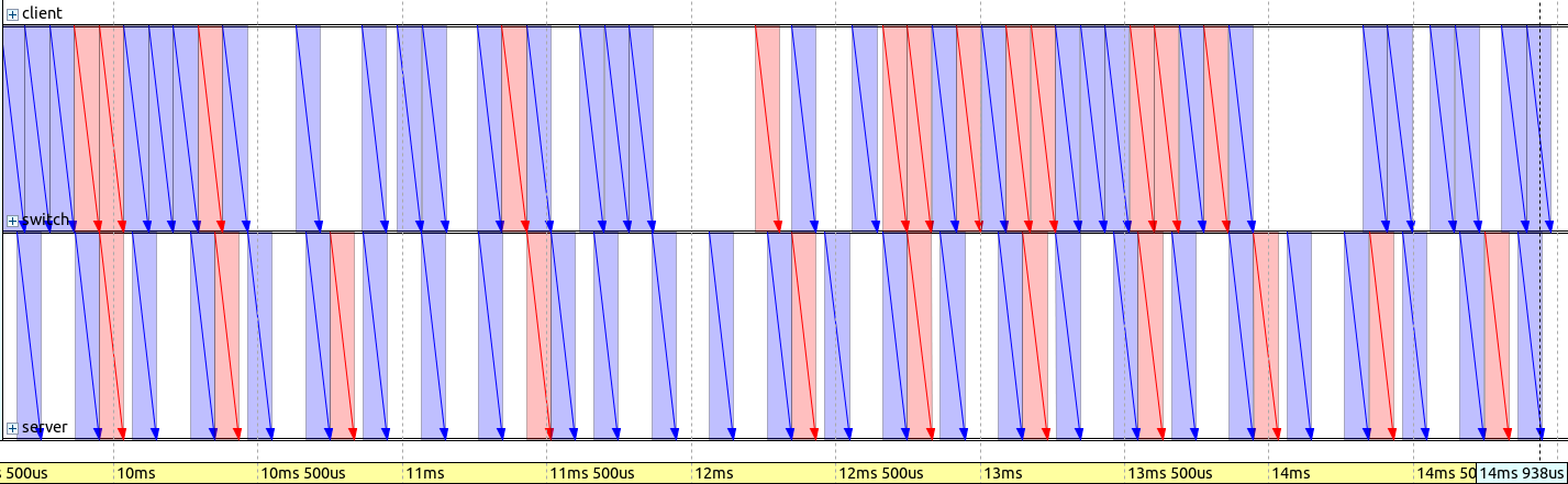
The traffic is bursty when it arrives in the switch. The traffic shaper within the switch evenly distributes the packets and interleaves video packets with those of the best effort category.
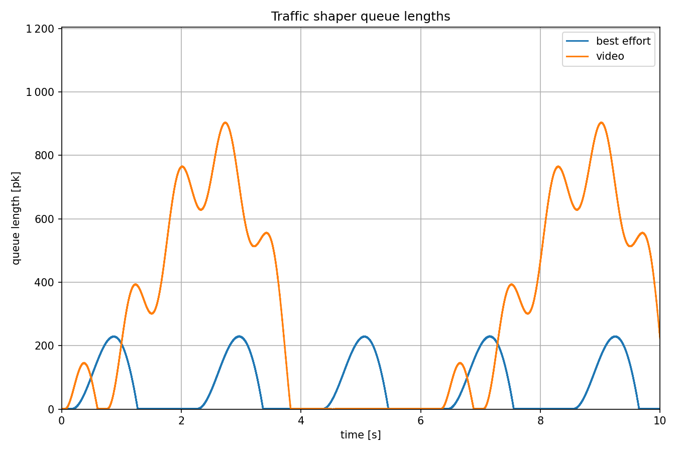
The next diagram illustrates the queue lengths of the traffic classes in the switch’s outgoing network interface. The queue lengths don’t increase over time, as the average data rate of the incoming traffic to the shaper is lower than the permitted data rate for outgoing traffic.
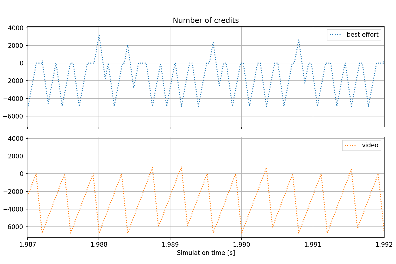
The following chart displays the rapid fluctuations in the number of credits. The number can exceed zero when the corresponding queue is not empty.
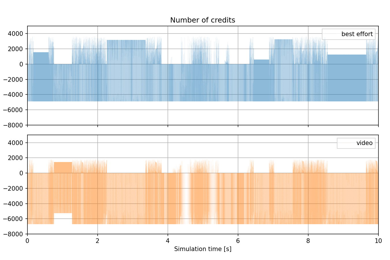
The next chart provides a closer view of the chart shown above, with a zoomed-in perspective:
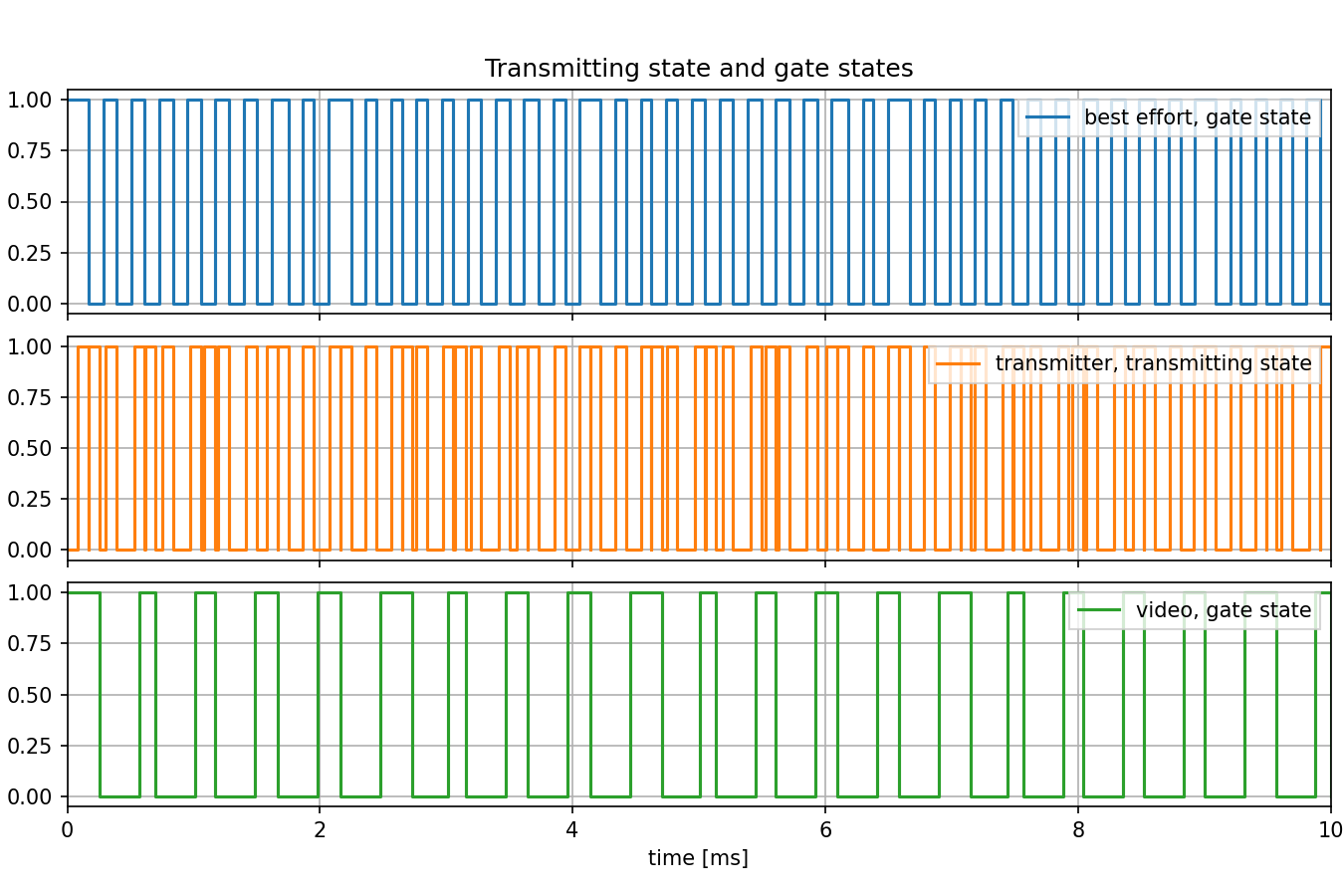
The following chart illustrates the gate states for the two credit-based shapers, as well as the transmitting state of the outgoing interface in the switch. It is worth noting that the gates can remain open for longer durations than a single packet transmission if the number of credits is zero or higher. Additionally, the transmitter is not in a constant transmitting state since the maximum outgoing data rate of the switch (~63Mbps) is lower than the channel capacity (100Mbps).
The following diagram depicts the relationships among the number of credits, the gate state of the credit-based transmission selection algorithm, and the transmitting state of the outgoing network interface for both traffic classes. To ensure visibility of the details, the diagram focuses on the first 2ms of the simulation:
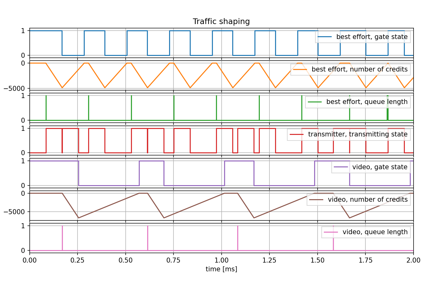
Note that the queue length remains at zero for most of the time since an incoming packet can be transmitted immediately without causing the queue length to increase to 1. Additionally, in the transmitter, there are instances where two packets (each from a different traffic class) are transmitted consecutively, with only an Interframe Gap period between them. For example, this can be observed in the first two transmissions. It’s important to highlight that such back-to-back transmission of packets from different traffic classes does not result in bursting within individual traffic classes.
In this diagram, we can observe the operation of the credit-based shaper. Let’s consider the number of credits for the video traffic category as an example. Initially, the number of credits is at 0. Then, when a packet arrives at the queue and begins transmitting, the number of credits decreases. After the transmission completes, the number of credits begins to increase again. As the number of credits reaches 0 once more, another transmission starts, causing the number of credits to decrease once again.
Sources: omnetpp.ini
Try It Yourself
If you already have INET and OMNeT++ installed, start the IDE by typing
omnetpp, import the INET project into the IDE, then navigate to the
inet/showcases/tsn/trafficshaping/creditbasedshaper folder in the Project Explorer. There, you can view
and edit the showcase files, run simulations, and analyze results.
Otherwise, there is an easy way to install INET and OMNeT++ using opp_env, and run the simulation interactively.
Ensure that opp_env is installed on your system, then execute:
$ opp_env run inet-4.6 --init -w inet-workspace --install --build-modes=release --chdir \
   -c 'cd inet-4.6.*/showcases/tsn/trafficshaping/creditbasedshaper && inet'
This command creates an inet-workspace directory, installs the appropriate
versions of INET and OMNeT++ within it, and launches the inet command in the
showcase directory for interactive simulation.
Alternatively, for a more hands-on experience, you can first set up the workspace and then open an interactive shell:
$ opp_env install --init -w inet-workspace --build-modes=release inet-4.6
$ cd inet-workspace
$ opp_env shell
Inside the shell, start the IDE by typing omnetpp, import the INET project,
then start exploring.
Discussion
Use this page in the GitHub issue tracker for commenting on this showcase.