Step 10. Configuring a completely wireless network
Goals
This step demonstrates using the error rate metric for configuring static routes. It also demonstrates leaving the routing tables unconfigured, so that a dynamic routing protocol can configure them. The step consists of three parts:
Part A: Static routing based on the error rate metric
Part B: Unconfigured routing tables, prepared for MANET routing
Part C: Routing tables configured using AODV protocol
Part A: Static routing based on error rate metric
The topology of completely wireless networks is unclear in a static analysis. By default, the configurator assumes all nodes can directly talk to each other. When they can’t, the error rate metric can be used for automatic route configuration instead of the default hop count.
Configuration
This step uses the ConfiguratorD network, defined in
ConfiguratorD.ned. The network
looks like this:
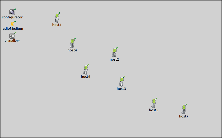
It contains seven AODVRouters laid out in a chain.
The configuration for this part in omnetpp.ini is the following:
[Config Step10A]
sim-time-limit = 100s
network = ConfiguratorD
description = "Completely wireless network, static routing based on error rate metric"

*.configurator.config = xmldoc("step10a.xml")

# Wireless settings
*.*.wlan[*].bitrate = 54Mbps
*.*.wlan[*].radio.transmitter.power = 1mW

*.visualizer.routingTableVisualizer.displayRoutingTables = true
*.visualizer.routingTableVisualizer.labelFormat = ""
*.visualizer.routingTableVisualizer.lineShiftMode = "none"
*.visualizer.routingTableVisualizer.destinationFilter = "*"
*.visualizer.mediumVisualizer.displayCommunicationRanges = true
The transmitter power of radios determines their communication range. The range is set up so that hosts are only in the range of the adjacent hosts in the chain. RoutingTableCanvasVisualizer is set to visualize routes to all destinations. The routing table visualization is simplified by turning off arrow labels and setting the arrow line shift to 0. The latter setting causes the visualizer to draw only one arrow between any nodes even if there would be multiple arrows, e.g. one for both directions (bi-directional routes will be displayed as bi-directional arrows now.) Communication ranges of all hosts will be displayed.
The transmission power outside the communication range is below the sensitivity of the receiving node, thus, the error rate is infinite. However, the fact that the receiving host is within the communication range circle doesn’t mean that it can receive the transmission correctly.
The XML configuration in step10a.xml is as follows:
<config>
	<interface hosts='**' address='10.x.x.x' netmask='255.x.x.x'/>
	<autoroute metric="errorRate"/>
</config>
It contains a copy of the default address configurations, and an <autoroute> element using the error rate metric. The configurator calculates the packet error rate for a Maximum Transfer Unit (MTU) sized packet. Edge costs in the connectivity graph are assigned accordingly.
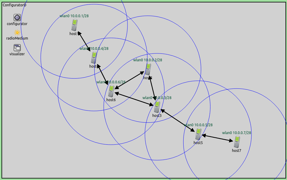
Results
Configured routes and communication ranges are displayed on the following image. Error rate outside the communication range is infinite, thus, all arrows are within the circles. Routes lead through adjacent hosts in the chain. In each segment of the path, correct reception is possible.
Part B: Unconfigured routing tables, prepared for MANET routing
Static routing is often not adequate in wireless networks, as the nodes might move and the topology can change. Dynamic routing protocols can react to these changes. When using dynamic protocols, the configurator is only used to configure the addresses. It leaves the routing table configuration to the dynamic protocol.
The configuration for this part in omnetpp.ini extends the one for Part A:
[Config Step10B]
sim-time-limit = 100s
extends = Step10A
description = "Completely wireless network, routing tables unconfigured, prepared for MANET routing"

*.configurator.addStaticRoutes = false
The configurator is instructed to leave the routing tables empty, by
setting addStaticRoutes to false. The configurator just assigns the
addresses according to the default XML configuration.
The visualizer is still set to visualize all routes towards all destinations.
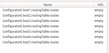
Results
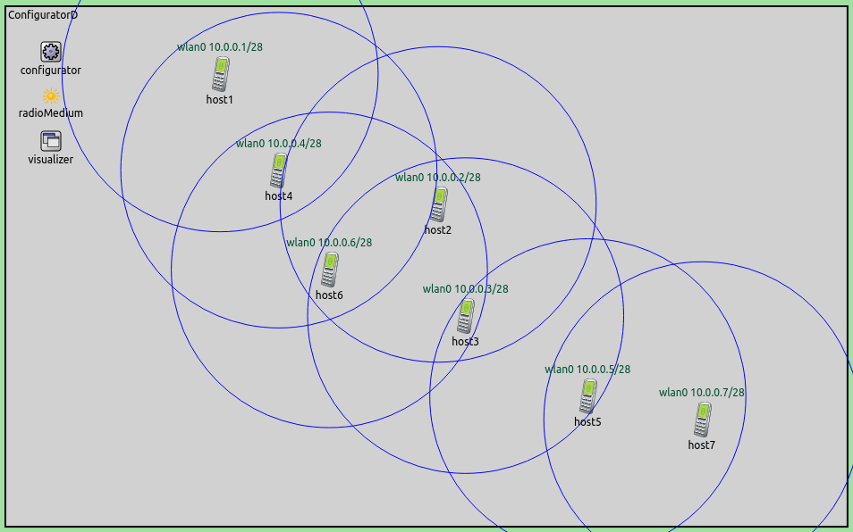
As instructed, the configurator didn’t add any routes, as indicated by the lack of arrows. The routing tables are empty.
Part C: Routing tables configured using AODV protocol
In this part, routing tables are set up by the Ad-hoc On-demand Distance Vector (AODV) dynamic routing protocol. The configuration for this part extends Part B. The configuration in omnetpp.ini is the following:
[Config Step10C]
sim-time-limit = 100s
extends = Step10B
description = "Completely wireless network, routing tables unconfigured, using AODV routing"

*.host1.numApps = 1
*.host1.app[0].typename = "PingApp"
*.host1.app[*].destAddr = "host7"
As specified in the previous part, the configurator is still instructed
not to add any routes. Also, the visualizer is still set to visualize
all routes. Additionally, host1 is set to ping host2. Since AODV
is a reactive routing protocol, the ping is required to trigger the AODV
protocol to set up routes.
Results
The routing tables are initially empty. The first ping packet triggers
AODV’s route discovery process, which eventually configures the routes.
AODV is a reactive protocol, so unused routes expire after a while. This
happens to the routes to host2, as it’s not in the path between
host1 and host7. This is displayed in the following video.
To record the video, the simulation was run in fast mode, thus, routes appear instantly. It takes a few seconds of simulation time for the unused routes to expire.
Sources: omnetpp.ini,
ConfiguratorD.ned
Discussion
Use this page in the GitHub issue tracker for commenting on this tutorial.