Step 1. Two hosts communicating wirelessly
Goals
In the first step, we want to create a network that contains two hosts, with one host sending a UDP data stream wirelessly to the other. Our goal is to keep the physical layer and lower layer protocol models as simple as possible.
We’ll make the model more realistic in later steps.
The model
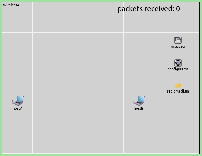
In this step, we’ll use the model depicted below.
Here is the NED source of the network:
network WirelessA
{
    parameters:
        @display("bgb=650,500;bgg=100,1,grey95");
        @figure[title](type=label; pos=0,-1; anchor=sw; color=darkblue);

        @figure[rcvdPkText](type=indicatorText; pos=380,20; anchor=w; font=,18; textFormat="packets received: %g"; initialValue=0);
        @statistic[packetReceived](source=hostB.app[0].packetReceived; record=figure(count); targetFigure=rcvdPkText);

    submodules:
        visualizer: <default(firstAvailableOrEmpty("IntegratedCanvasVisualizer"))> like IIntegratedVisualizer if typename != "" {
            @display("p=580,125");
        }
        configurator: Ipv4NetworkConfigurator {
            @display("p=580,200");
        }
        radioMedium: RadioMedium {
            @display("p=580,275");
        }
        hostA: <default("WirelessHost")> like INetworkNode {
            @display("p=50,325");
        }
        hostB: <default("WirelessHost")> like INetworkNode {
            @display("p=450,325");
        }
}
We’ll explain the above NED file below.
The playground
The model contains a playground of the size 500x650 meters, with two hosts spaced 400 meters apart. (The distance will be relevant in later steps.) These numbers are set via display strings.
The modules that are present in the network in addition to the hosts are responsible for tasks like visualization, configuring the IP layer, and modeling the physical radio channel. We’ll return to them later.
The hosts
In INET, hosts are usually represented with the StandardHost NED type, which is a generic template for TCP/IP hosts. It contains protocol components like TCP, UDP and IP, slots for plugging in application models, and various network interfaces (NICs). StandardHost has some variations in INET, for example, WirelessHost, which is basically a StandardHost preconfigured for wireless scenarios.
As you can see, the hosts’ type is parametric in this NED file (defined
via a hostType parameter and the INetworkNode module interface).
This is done so that in later steps we can replace hosts with a
different NED type. The actual NED type here is WirelessHost (given
near the top of the NED file), and later steps will override this
setting using omnetpp.ini.
Address assignment
IP addresses are assigned to hosts by an Ipv4NetworkConfigurator
module, which appears as the configurator submodule in the network.
The hosts also need to know each others’ MAC addresses to communicate,
which in this model is taken care of by using per-host GlobalArp
modules instead of real ARP.
Traffic model
In the model, host A generates UDP packets that are received by host B. To this end, host A is configured to contain a UdpBasicApp module, which generates 1000-byte UDP messages at random intervals with exponential distribution, the mean of which is 12ms. Therefore the app is going to generate 100 kbyte/s (800 kbps) UDP traffic, not counting protocol overhead. Host B contains a UdpSink application that just discards received packets.
The model also displays the number of packets received by host B. The
text is added by the @figure[rcvdPkText] line, and the subsequent
line arranges the figure to be updated during the simulation.
Physical layer modeling
Let us concentrate on the module called radioMedium. All wireless
simulations in INET need a radio medium module. This module represents
the shared physical medium where communication takes place. It is
responsible for taking signal propagation, attenuation, interference,
and other physical phenomena into account.
INET can model the wireless physical layer at various levels of detail, realized with different radio medium modules. In this step, we use UnitDiskRadioMedium, which is the simplest model. It implements a variation of unit disc radio, meaning that physical phenomena like signal attenuation are ignored, and the communication range is simply specified in meters. Transmissions within range are always correctly received unless collisions occur. Modeling collisions (overlapping transmissions causing reception failure) and interference range (a range where the signal cannot be received correctly, but still collides with other signals causing their reception to fail) are optional.
NOTE: Naturally, this model of the physical layer has little correspondence to reality. However, it has its uses in the simulation. Its simplicity and consequent predictability are an advantage in scenarios where realistic modeling of the physical layer is not a primary concern, for example in the modeling of ad-hoc routing protocols. Simulations using UnitDiskRadioMedium also run faster than more realistic ones, due to the low computational cost.
In hosts, network interface cards are represented by NIC modules. Radio
is part of wireless NIC modules. There are various radio modules, and
one must always use one that is compatible with the medium module. In
this step, hosts contain GenericUnitDiskRadio as part of
AckingWirelessInterface.
In this model, we configure the chosen physical layer model
(UnitDiskRadioMedium and GenericUnitDiskRadio) as follows. The
communication range is set to 500m. Modeling packet losses due to
collision (termed “interference” in this model) is turned off, resulting
in pairwise independent duplex communication channels. The radio data
rates are set to 1 Mbps. These values are set in omnetpp.ini with
the communicationRange, ignoreInterference, and bitrate
parameters of the appropriate modules.
MAC layer
NICs modules also contain an L2 (i.e. data link layer) protocol. The MAC
protocol in AckingWirelessInterface is configurable, the default choice
being MultipleAccessMac. MultipleAccessMac implements a trivial
MAC layer which only provides encapsulation/decapsulation but no real
medium access protocol. There is virtually no medium access control:
packets are transmitted as soon as the previous packet has completed
transmission. MultipleAccessMac also contains an optional
out-of-band acknowledgment mechanism which we turn off here.
The configuration:
[Config Wireless01]
description = Two hosts communicating wirelessly
network = WirelessA
sim-time-limit = 20s

*.radioMedium.signalAnalogRepresentation = "unitDisk"
*.host*.ipv4.arp.typename = "GlobalArp"

*.hostA.numApps = 1
*.hostA.app[0].typename = "UdpBasicApp"
*.hostA.app[0].destAddresses = "hostB"
*.hostA.app[0].destPort = 5000
*.hostA.app[0].messageLength = 1000B
*.hostA.app[0].sendInterval = exponential(12ms)
*.hostA.app[0].packetName = "UDPData"

*.hostB.numApps = 1
*.hostB.app[0].typename = "UdpSink"
*.hostB.app[0].localPort = 5000

*.host*.wlan[0].typename = "AckingWirelessInterface"
*.host*.wlan[0].mac.useAck = false
*.host*.wlan[0].mac.fullDuplex = false
*.host*.wlan[0].radio.signalAnalogRepresentation = "unitDisk"
*.host*.wlan[0].radio.transmitter.analogModel.communicationRange = 500m
*.host*.wlan[0].radio.receiver.ignoreInterference = true
*.host*.wlan[0].mac.headerLength = 23B

*.host*.**.bitrate = 1Mbps
Results
When we run the simulation, here’s what happens. Host A’s UdpBasicApp generates UDP packets at random intervals. These packets are sent down via UDP and IPv4 to the network interface for transmission. The network interface queues packets and transmits them as soon as it can. As long as there are packets in the network interface’s transmission queue, packets are transmitted back-to-back, with no gaps between subsequent packets.
These events can be followed on OMNeT++’s Qtenv runtime GUI. The
following image has been captured from Qtenv, and shows the inside of
host A during the simulation. One can see a UDP packet being sent down
from the udpApp submodule, traversing the intermediate protocol
layers, and being transmitted by the wlan interface.
The next animation shows the communication between the hosts, using OMNeT++’s default “message sending” animation.
When the simulation concludes at t=25s, the packet count meter indicates that around 2000 packets were sent. A packet with overhead is 1028 bytes, which means the transmission rate was around 660 kbps.
Number of packets received by host B: 2017
Sources: omnetpp.ini,
WirelessA.ned
Discussion
Use this page in the GitHub issue tracker for commenting on this tutorial.