The Hidden Node Problem
Goals
The hidden node problem occurs when two nodes in a wireless network can communicate with a third node, but cannot communicate with each other directly due to obstacles or being out of range. This can lead to collisions at the third node when both nodes transmit simultaneously. The RTS/CTS mechanism is used to address this problem by allowing nodes to reserve the channel before transmitting.
In this showcase, we demonstrate the hidden node problem and how the RTS/CTS mechanism can be used to solve it in an 802.11 wireless network.
4.0Description of the hidden node problem
The hidden node problem is the collective name of situations where a transmitting node does not know about the existence of another node (the “hidden node”) while transmitting to a third node which is within the range of both nodes. Since the node doesn’t know when the hidden node is transmitting, normal collision avoidance is not effective, and their transmissions will often collide at the third node. The hidden node problem reduces channel utilization and damages network performance. Hidden nodes may be created by distance, by obstacles that block radio signals, by unequal transmission powers, or by other factors. The situation may be symmetric or asymmetric (the roles of the originator and the hidden node may or may not be interchangeable.) You can read more about the hidden node problem e.g. here.
The 802.11 protocol allows transmissions to be protected against interference from other stations by using the RTS/CTS mechanism. Using RTS/CTS, the node wishing to transmit first sends an RTS (Request To Send) frame to the target node. The target node, if the channel is clear, responds with a CTS (Clear To Send) frame that not only informs the originator that it may transmit but also tells other stations to refrain from using the channel for the specified amount of time. RTS/CTS obviously adds some overhead to the transmission process, so it is normally used to protect longer frames which are more expensive to retransmit. RTS/CTS does not completely solve the hidden node problem, but it can significantly help under certain conditions. A slightly more in-depth coverage of RTS/CTS and challenges associated with it can be found e.g. here.
Demonstrating the hidden node problem
In this showcase, we’ll set up a wireless network that contains a hidden node. To ensure that two selected nodes don’t hear one another, we’ll place an obstacle (a section of wall that blocks radio signals) between them. We’ll run the simulation without RTS/CTS, with RTS/CTS turned on, and for reference, also with the wall removed.
The model
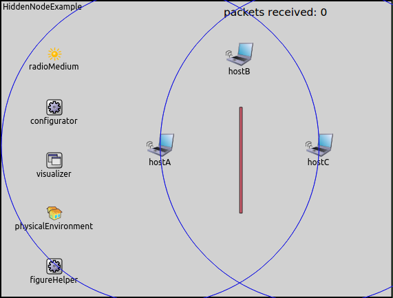
The network for all simulations contains three hosts, arranged in a triangle. Host A and C are separated by a wall that completely blocks transmissions, thus the nodes cannot transmit to each other, and cannot sense when the other is transmitting. The wall is enabled or disabled in the various simulations. Hosts A and C both send UDP packets to Host B, which is able to receive the transmissions of both hosts.
The RTS/CTS mechanism can be enabled or disabled by setting the
rtsThresholdBytes parameter in the mac submodule of hosts. The
RTS/CTS mechanism is used for transmitting frames whose size exceeds the
threshold.
We will run the simulation in four configurations:
WallOnRtsOff: RTS/CTS mechanism disabledWallOnRtsOn: RTS/CTS mechanism enabledWallOffRtsOff: Wall removed, no RTS/CTSWallOffRtsOn: Wall removed, RTS/CTS on
In all configurations, hosts A and C will both send constant size (1000-byte) UDP packets at a rate that saturates the MAC most of the time. The transmission power and all other parameters of the two hosts are identical. We will run each configuration for the same simulation time interval (5 seconds), and count the number of packets received by Host B.
Results
RTS/CTS disabled
Both Host A and C frequently transmit simultaneously, thus the number of collisions at Host B is high.
The animation below depicts such a collision. Host C starts transmitting, and Host A starts transmitting as well before Host C’s transmission is over. As neither packet can be received correctly by Host B (and thus they are not ACKed), Hosts A and C retry transmitting the same packet multiple times after the backoff period. The retransmitted packets also collide, because the packets are long compared to the backoff period. Finally, Host C manages to send its packet without interference.
Here is what a collision looks like in the log:
The number of packets received by Host B (RTS/CTS off): 1470
RTS/CTS enabled
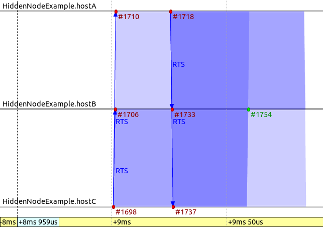
With RTS/CTS enabled, there are no more collisions, except for RTS frames. RTS and CTS frames are much shorter than data frames (about 34us vs 1.45ms), thus the probability of RTS frames colliding is less than for data frames. The result is that a low number of RTS frames collide, and since they are short, the collisions don’t take up much time.
The following sequence chart has been recorded from the simulation and depicts an RTS collision.
The following animation shows the RTS/CTS and data frame exchange.
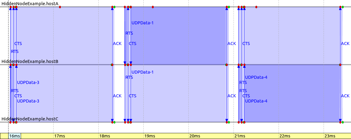
The following sequence chart illustrates that the RTS/CTS mechanism makes the communication more coordinated, as the nodes know when to transmit to avoid collisions. It also illustrates that RTS and CTS frames are much shorter than data frames.
The number of received packets at Host B (RTS/CTS on): 1971
Wall removed
With the wall removed, hidden nodes are no longer a problem. When the RTS/CTS mechanism is not used, collision avoidance mechanisms can work, and the number of collisions is low. The RTS/CTS mechanism stops data frame collisions, so only the RTS and CTS frames can collide. The RTS and CTS frames are much shorter than data frames, thus retransmitting them takes less time. Even though the RTS/CTS frames contribute some overhead, more packets are received correctly at Host B. When RTS/CTS is used, the number of packets received correctly at Host B is approximately the same regardless of the presence of the wall.
The number of received packets at Host B (wall removed, RTS/CTS off): 1966 The number of received packets at Host B (wall removed, RTS/CTS on): 1987
Sources: omnetpp.ini, HiddenNodeShowcase.ned
Try It Yourself
If you already have INET and OMNeT++ installed, start the IDE by typing
omnetpp, import the INET project into the IDE, then navigate to the
inet/showcases/wireless/hiddennode folder in the Project Explorer. There, you can view
and edit the showcase files, run simulations, and analyze results.
Otherwise, there is an easy way to install INET and OMNeT++ using opp_env, and run the simulation interactively.
Ensure that opp_env is installed on your system, then execute:
$ opp_env run inet-4.0 --init -w inet-workspace --install --chdir \
   -c 'cd inet-4.0.*/showcases/wireless/hiddennode && inet'
This command creates an inet-workspace directory, installs the appropriate
versions of INET and OMNeT++ within it, and launches the inet command in the
showcase directory for interactive simulation.
Alternatively, for a more hands-on experience, you can first set up the workspace and then open an interactive shell:
$ opp_env install --init -w inet-workspace inet-4.0
$ cd inet-workspace
$ opp_env shell
Inside the shell, start the IDE by typing omnetpp, import the INET project,
then start exploring.


