Effects of Time Synchronization on Time-Aware Shaping
Goals
In this showcase, we demonstrate how time synchronization affects end-to-end delay in a network that is using time-aware traffic shaping.
Note
This showcase builds upon the Clock Drift, Using gPTP and Time-Aware Shaping showcases.
4.6The Model
Overview
The showcase contains a network that uses time-aware shaping and inaccurate local clocks in each network node. Time-aware shaping requires synchronized time among all network nodes, so we also use gPTP for time synchronization. This results in a constant end-to-end delay for the traffic. We examine how failure and recovery in time synchronization affect the delay.
If time synchronization fails for some reason, such as the primary clock going offline, time-aware shaping cannot guarantee bounded delays any longer. Time synchronization can continue, and delay guarantees can be met, however, if all network nodes switch over to a secondary master clock.
To demonstrate this, we present three cases, with three configurations:
Normal operation: time synchronization works, and the delay is constant (this is the same case as in the last configuration in the Using gPTP showcase).
Failure of the master clock: the master clock disconnects from the network, and time is not synchronized anymore.
Failover to a secondary master clock: the master clock disconnects from the network, but time synchronization can continue because network nodes switch to the secondary master clock.
The Configuration
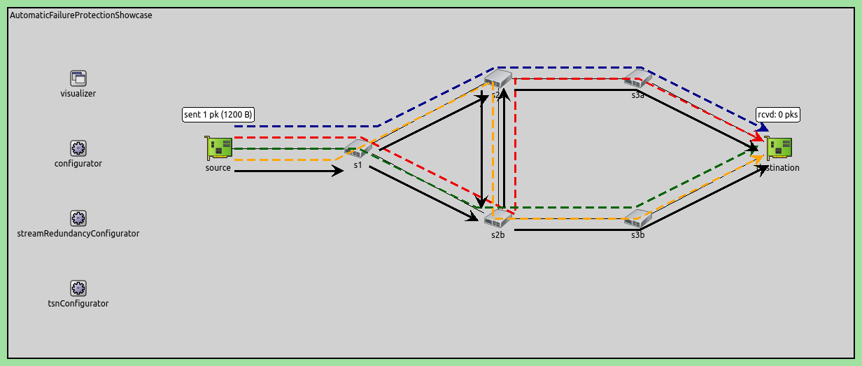
All simulations in the showcase use the same network as in the Two Master Clocks Exploiting Network Redundancy section of the Using gPTP showcase. The network contains TsnDevice and TsnClock modules connected to a ring of switches (TsnSwitch):
Most settings, such as traffic generation, time-aware shaping, clock drift, gPTP
domains, and visualization, are shared between the three cases, and are
specified in the General configuration. The following sections present these
settings.
Traffic
Traffic in the network consists of UDP packets sent between tsnDevice1 and
tsnDevice4, and gPTP messages sent by all nodes. To generate the UDP
application traffic, we configure tsnDevice1 to send 10B UDP packets to
tsnDevice2:
*.tsnDevice1.numApps = 1
*.tsnDevice1.app[0].typename = "UdpSourceApp"
*.tsnDevice1.app[0].source.packetLength = 10B
*.tsnDevice1.app[0].source.productionInterval = 1ms
*.tsnDevice1.app[0].io.destAddress = "tsnDevice4"
*.tsnDevice1.app[0].io.destPort = 1000
*.tsnDevice1.app[0].source.clockModule = "^.^.clock"
Clocks and Clock Drift
Clocks use MultiClock and SettableClock modules with constant drift oscillators. We set the initial drift rate and the drift rate change with a random uniform distribution, and limit the drift rate change:
**.oscillator.typename = "RandomDriftOscillator"
*.tsnClock2.clock.clock[*].oscillator.initialDriftRate = -30ppm
**.oscillator.nominalTickLength = 10ns
**.oscillator.initialDriftRate = uniform(-50ppm, 50ppm)
**.oscillator.driftRateChange = uniform(-20ppm, 20ppm)
**.oscillator.changeInterval = uniform(10ms, 50ms)
**.oscillator.driftRateChangeLowerLimit = -50ppm
**.oscillator.driftRateChangeUpperLimit = 50ppm
Time-Aware Shaping
Here is the time-aware shaping part of the configuration:
*.tsnSwitch*.hasEgressTrafficShaping = true
*.tsnSwitch*.eth[*].macLayer.queue.numTrafficClasses = 2
*.tsnSwitch*.eth[*].macLayer.queue.classifier.typename = "ContentBasedClassifier"
*.tsnSwitch*.eth[*].macLayer.queue.queue[*].typename = "DropTailQueue"
*.tsnSwitch*.eth[*].macLayer.queue.classifier.packetFilters = ["app*", "Gptp*"]
*.tsnSwitch*.eth[*].macLayer.queue.transmissionGate[0].durations = [100us, 900us]
*.tsnSwitch*.eth[*].macLayer.queue.transmissionGate[0].clockModule = "^.^.^.^.clock"
*.tsnSwitch*.eth[*].macLayer.queue.transmissionGate[1].initiallyOpen = false
*.tsnSwitch*.eth[*].macLayer.queue.transmissionGate[1].durations = [100us, 900us]
*.tsnSwitch*.eth[*].macLayer.queue.transmissionGate[1].clockModule = "^.^.^.^.clock"
We enable time-aware shaping in all switches. We configure two traffic classes: one for gPTP messages, and one for UDP packets. The gPTP messages are critical to maintain time synchronization in the network, so we configure the time-aware shapers to allocate 90% of time to them. Gates for the UDP packets are configured to be open 10% of the time, so the UDP traffic is limited to 10Mbps. The UDP traffic data rate is 10kbps, so there is a lot of room in the send window; this makes the setup more tolerant of clock drift between network nodes.
Note
The traffic class priority doesn’t affect the operation, because the two gates are never open simultaneously.
gPTP
For time synchronization, we use the same clock and gPTP setup as in the Two
Master Clocks Exploiting Network Redundancy configuration in the
Using gPTP showcase. To summarize,
we have a primary and a hot-standby master clock node (tsnClock1 and
tsnClock2, respectively). Each master clock has two gPTP time domains, and
each gPTP domain disseminates timing information in the ring of switches in
opposing directions. All bridge and slave nodes are part of all four time
domains. With this setup, time synchronization is protected against the failure
of one master clock, and the failure of any link between the switches. The two
gPTP domains of the hot-standby master clock synchronize to the two domains of
the primary master. The switches and the devices have four gPTP domains, and
four up-to-date clocks during normal operation.
Note
Here is the gPTP configuration for reference:
click to open/close
*.tsnClock2.clock.typename = "MultiClock"
*.tsnClock2.clock.numClocks = 2

# TSN clocks have multiple gPTP time synchronization domains
*.tsnClock*.gptp.typename = "MultiDomainGptp"
*.tsnClock1.gptp.numDomains = 2
*.tsnClock1.gptp.domain[0..1].clockModule = "tsnClock1.clock"
*.tsnClock1.gptp.domain[0].masterPorts = ["eth0"]
*.tsnClock1.gptp.domain[1].masterPorts = ["eth0"]
*.tsnClock2.gptp.numDomains = 4
*.tsnClock2.gptp.domain[2..3].clockModule = "tsnClock2.clock"
*.tsnClock2.gptp.domain[0].gptpNodeType = "SLAVE_NODE"
*.tsnClock2.gptp.domain[0].slavePort = "eth0"
*.tsnClock2.gptp.domain[1].gptpNodeType = "SLAVE_NODE"
*.tsnClock2.gptp.domain[1].slavePort = "eth0"
*.tsnClock2.gptp.domain[2].gptpNodeType = "MASTER_NODE"
*.tsnClock2.gptp.domain[2].masterPorts = ["eth0"]
*.tsnClock2.gptp.domain[3].gptpNodeType = "MASTER_NODE"
*.tsnClock2.gptp.domain[3].masterPorts = ["eth0"]

# TSN switches have multiple clocks
*.tsnSwitch*.clock.typename = "MultiClock"
*.tsnSwitch*.clock.numClocks = 4

# TSN switches have multiple gPTP time synchronization domains
*.tsnSwitch*.gptp.typename = "MultiDomainGptp"
*.tsnSwitch*.gptp.numDomains = 4

# TSN switch 1
*.tsnSwitch1.gptp.domain[0].masterPorts = ["eth1"]
*.tsnSwitch1.gptp.domain[0].slavePort = "eth0"
*.tsnSwitch1.gptp.domain[1].masterPorts = ["eth2"]
*.tsnSwitch1.gptp.domain[1].slavePort = "eth0"
*.tsnSwitch1.gptp.domain[2].masterPorts = ["eth1"]
*.tsnSwitch1.gptp.domain[2].slavePort = "eth2"
*.tsnSwitch1.gptp.domain[3].masterPorts = ["eth2"]
*.tsnSwitch1.gptp.domain[3].slavePort = "eth1"

# TSN switch 2
*.tsnSwitch2.gptp.domain[0].masterPorts = ["eth1", "eth2"]
*.tsnSwitch2.gptp.domain[0].slavePort = "eth0"
*.tsnSwitch2.gptp.domain[1].masterPorts = ["eth2"]
*.tsnSwitch2.gptp.domain[1].slavePort = "eth1"
*.tsnSwitch2.gptp.domain[2].masterPorts = ["eth1", "eth2"]
*.tsnSwitch2.gptp.domain[2].slavePort = "eth0"
*.tsnSwitch2.gptp.domain[3].masterPorts = ["eth0", "eth2"]
*.tsnSwitch2.gptp.domain[3].slavePort = "eth1"

# TSN switch 3
*.tsnSwitch3.gptp.domain[0].masterPorts = ["eth1", "eth2"]
*.tsnSwitch3.gptp.domain[0].slavePort = "eth0"
*.tsnSwitch3.gptp.domain[1].masterPorts = ["eth0", "eth2"]
*.tsnSwitch3.gptp.domain[1].slavePort = "eth1"
*.tsnSwitch3.gptp.domain[2].masterPorts = ["eth2"]
*.tsnSwitch3.gptp.domain[2].slavePort = "eth0"
*.tsnSwitch3.gptp.domain[3].masterPorts = ["eth0", "eth2"]
*.tsnSwitch3.gptp.domain[3].slavePort = "eth1"

# TSN switch 4
*.tsnSwitch4.gptp.domain[0].masterPorts = ["eth0", "eth2"]
*.tsnSwitch4.gptp.domain[0].slavePort = "eth1"
*.tsnSwitch4.gptp.domain[1].masterPorts = ["eth0", "eth1"]
*.tsnSwitch4.gptp.domain[1].slavePort = "eth2"
*.tsnSwitch4.gptp.domain[2].masterPorts = ["eth2"]
*.tsnSwitch4.gptp.domain[2].slavePort = "eth0"
*.tsnSwitch4.gptp.domain[3].masterPorts = ["eth1"]
*.tsnSwitch4.gptp.domain[3].slavePort = "eth0"

# TSN switch 5
*.tsnSwitch5.gptp.domain[0].masterPorts = ["eth1", "eth2"]
*.tsnSwitch5.gptp.domain[0].slavePort = "eth0"
*.tsnSwitch5.gptp.domain[1].masterPorts = ["eth0", "eth2"]
*.tsnSwitch5.gptp.domain[1].slavePort = "eth1"
*.tsnSwitch5.gptp.domain[2].masterPorts = ["eth1", "eth2"]
*.tsnSwitch5.gptp.domain[2].slavePort = "eth0"
*.tsnSwitch5.gptp.domain[3].masterPorts = ["eth2"]
*.tsnSwitch5.gptp.domain[3].slavePort = "eth1"

# TSN switch 6
*.tsnSwitch6.gptp.domain[0].masterPorts = ["eth2"]
*.tsnSwitch6.gptp.domain[0].slavePort = "eth0"
*.tsnSwitch6.gptp.domain[1].masterPorts = ["eth0", "eth2"]
*.tsnSwitch6.gptp.domain[1].slavePort = "eth1"
*.tsnSwitch6.gptp.domain[2].masterPorts = ["eth1", "eth2"]
*.tsnSwitch6.gptp.domain[2].slavePort = "eth0"
*.tsnSwitch6.gptp.domain[3].masterPorts = ["eth0", "eth2"]
*.tsnSwitch6.gptp.domain[3].slavePort = "eth1"

# TSN devices have multiple clocks
*.tsnDevice*.clock.typename = "MultiClock"
*.tsnDevice*.clock.numClocks = 4

# TSN devices have multiple gPTP time synchronization domains
*.tsnDevice*.gptp.typename = "MultiDomainGptp"
*.tsnDevice*.gptp.numDomains = 4
*.tsnDevice1.gptp.clockModule = "tsnDevice1.clock"
*.tsnDevice2.gptp.clockModule = "tsnDevice2.clock"
*.tsnDevice3.gptp.clockModule = "tsnDevice3.clock"
*.tsnDevice4.gptp.clockModule = "tsnDevice4.clock"
*.tsnDevice*.gptp.domain[*].slavePort = "eth0"

# different initial gPTP pdelay measurement and time synchronization offsets
**.pdelayInitialOffset = 0.1ms
*.*.gptp.domain[0].syncInitialOffset = syncInterval * 1 / 4
*.*.gptp.domain[1].syncInitialOffset = syncInterval * 2 / 4
*.*.gptp.domain[2].syncInitialOffset = syncInterval * 3 / 4
*.*.gptp.domain[3].syncInitialOffset = syncInterval * 4 / 4
In the next section, we examine the simulation results for the three cases.
Example Simulations and Results
Normal Operation
In this configuration, time synchronization is operating properly. The
configuration for this case is empty (only the General configuration
applies):
[Config NormalOperation]
description = "Normal operation of time-aware shaping with time synchronization"
Let us examine the clock drift (i.e., clock time difference to simulation time) and the end-to-end delay. The following chart displays the clock drift for clocks in gPTP time domain 0 (one of the gPTP domains of the primary master). This is the active gPTP time domain in all network nodes (i.e., all nodes keep time according to this gPTP time domain):
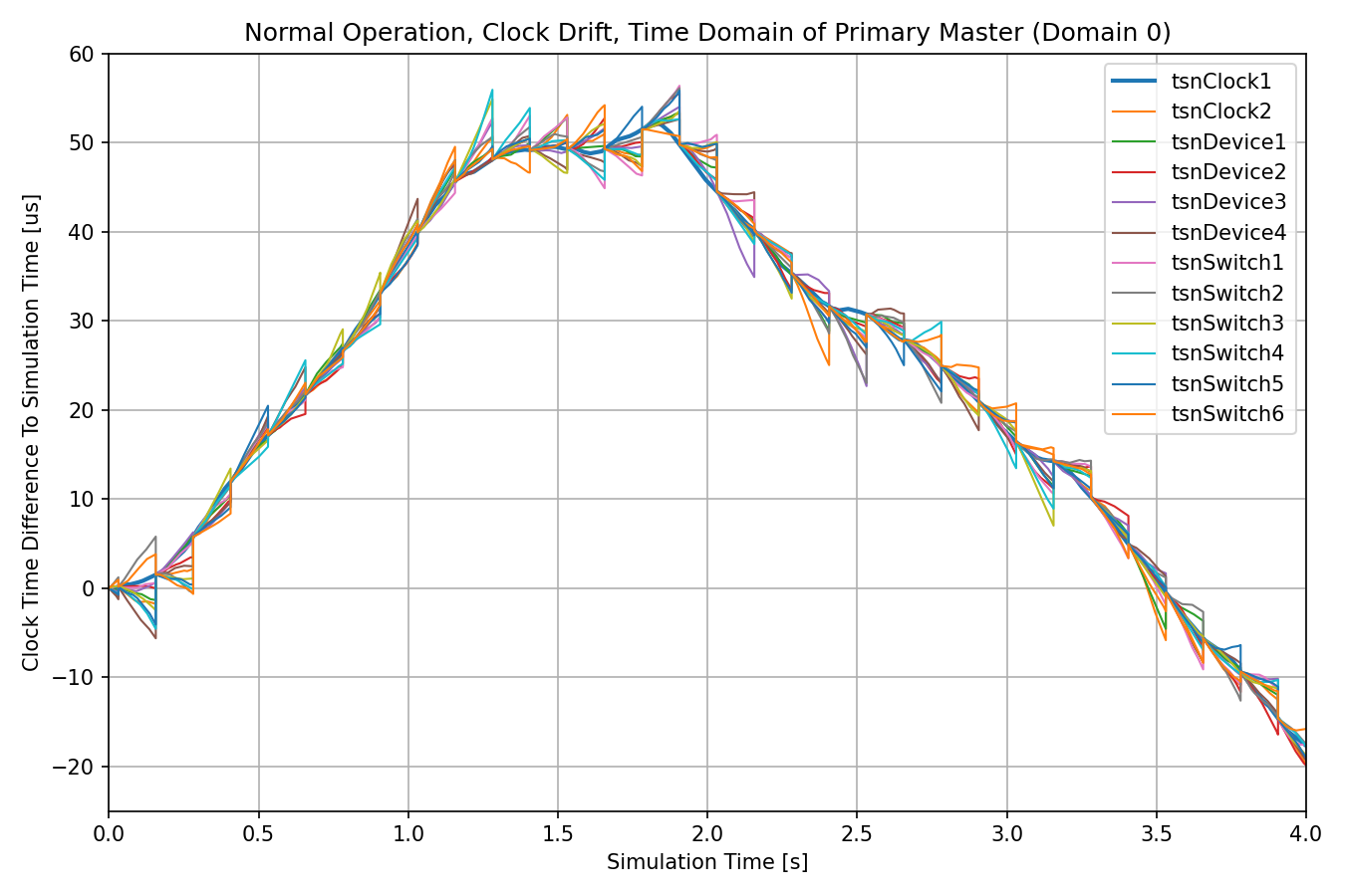
Due to everything in the network operating properly, bridge and slave nodes periodically synchronize their clock time and drift rate to the primary master node. However, due to the randomly changing drift rates, they diverge from the master clock after some time.
Note
The other three gPTP time domains are maintained simultaneously but not used.
The next chart displays the clock drift for gPTP time domain 2, where timing information originates from the hot-standby master clock. All bridge and slave nodes synchronize to the hot-standby master (thick orange line), which in turn synchronizes to the primary master (dotted blue line) in another gPTP domain:
Note
In this configuration, this time domain is not used by applications or the time-aware shaping. Later on, this time domain will be important because clocks will fail over to it.
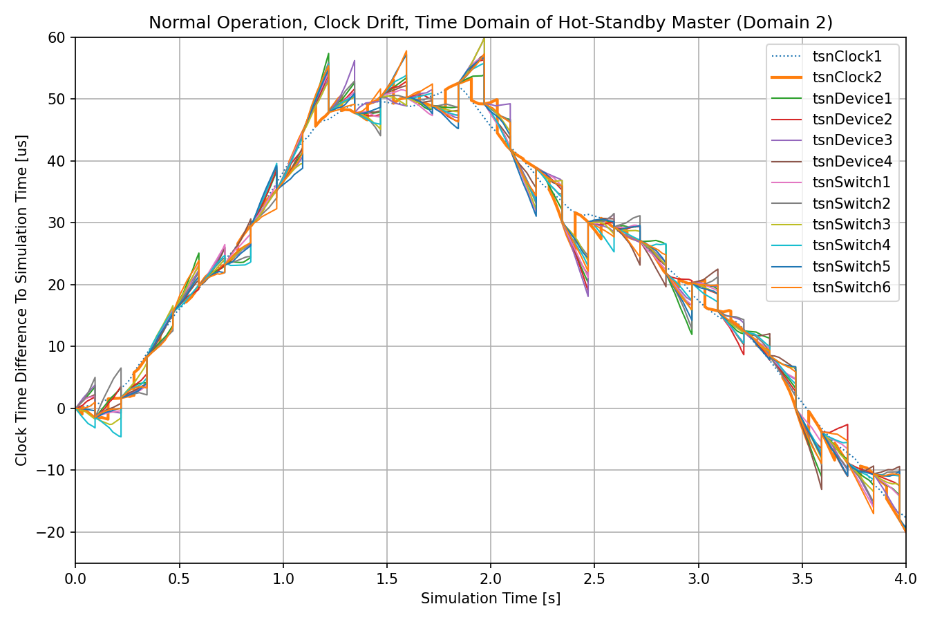
Note that bridge and slave nodes update their time when the hot-standby master node’s clock has already drifted from the primary master.
The next chart displays the end-to-end delay of application traffic, which is mostly a constant low value:
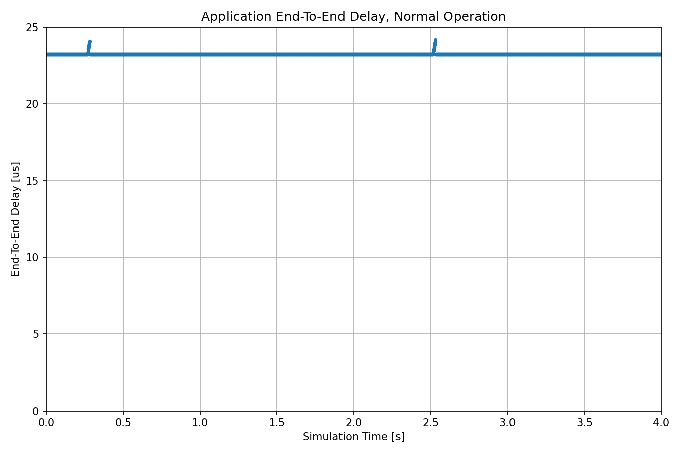
In the next section, we examine what happens if we take the master clock node offline during the simulation.
Link Failure of Master Clock
In this configuration, the time synchronization of the two time domains of the primary master clock stop due to a link failure of the primary master clock (the other two time domains are still synchronized). After the link break, the active clocks in the network begin to diverge from each other.
We schedule the link break at 2s (halfway through the simulation) with a scenario manager script. Here is the configuration:
[Config LinkFailure]
description = "Master clock link failure effects on time-aware shaping"
extends = NormalOperation

# TSN clock1 disconnects from the network at 2 seconds
*.scenarioManager.script = xml("<scenario> \
                                  <at t='2'> \
                                    <disconnect src-module='tsnClock1' src-gate='ethg[0]'/> \
                                  </at> \
                                </scenario>")
As in the previous section, we take a look at clock drift and end-to-end delay. The next chart shows the clock drift of gPTP time domain 0:
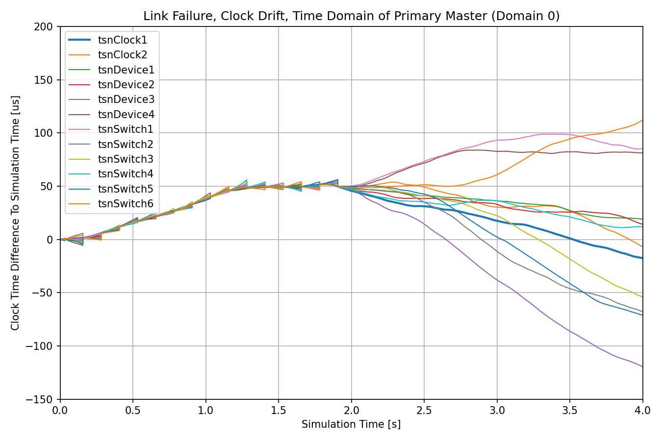
The clocks begin to diverge after time synchronization in this gPTP time domain stops.
The next chart shows clock drift in time domain 2. This is the time domain of the hot-standby master clock, which stays online, so the clocks in this time domain keep being synchronized. (the hot-standby master is denoted with a thick orange line, the primary master with a dotted blue line.)
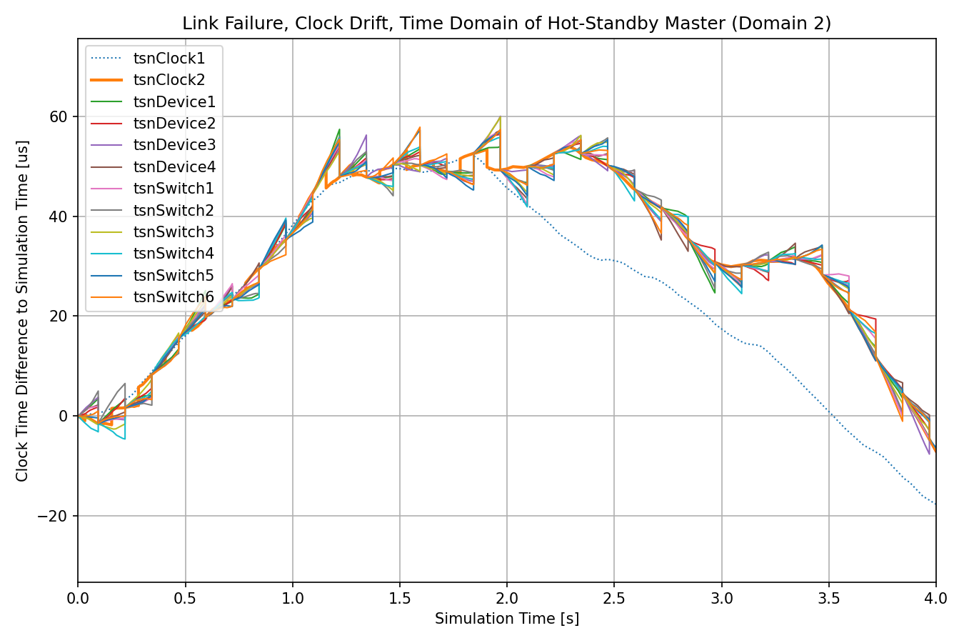
When the primary master node goes offline, the hot-standby master node cannot synchronize to it anymore, its clock drifts from the primary master’s, shown by the orange and blue lines diverging. The bridge and slave nodes continue to synchronize to the hot-standby master node (shown by the other lines following the hot-standby master node).
The active clocks in bridge and slave nodes are the ones that use time domain 0 as the source of time, thus the clock drift chart for the active clocks is the same as the one displaying clock drift for time domain 0.
The next chart shows the delay:
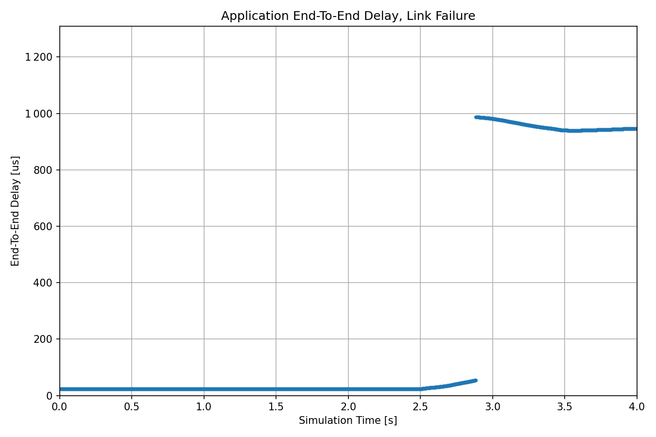
After the clock divergence grows above a certain value, the end-to-end delay suddenly increases dramatically. The reason is that frames often wait for the next gate scheduling cycle because they miss the allocated time slot due to improperly synchronized clocks. The delay increases from the nominal microsecond-range to millisecond range. Needless to say, in this scenario, the constant low delay cannot be guaranteed.
In the next section, we examine what happens if time synchronization can continue after the link break due to failover to the hot-standby master clock.
Failover to Hot-Standby Clock
In this configuration, we take the primary master clock offline just as in the previous one, but we also switch the active clock in each node over to the one that synchronizes with the hot-standby master (gPTP time domain 2 as mentioned previously), so time synchronization can continue to keep the difference in clocks in the network below the required limit.
Note
There is no difference in time synchronization at all in the three configurations. The difference is in which clocks/domains are active.
We schedule the link break with a scenario manager script. We also schedule changing the active clock parameter in the MultiClock modules in all nodes. Both changes are scheduled at 2s, halfway through the simulation:
Note
We schedule the two changes at the same time, 2s. This is unrealistic. There is no mechanism here that detects the breakage of the time synchronization domains, so we switch the active clock manually with the scenario manager. Even if there was such a mechanism, switching to another time domain at exactly the same moment as the link break happens is unrealistic as well.
[Config Failover]
description = "Hot-standby master clock takes over time synchronization"
extends = LinkFailure

# TSN clock1 disconnects from the network at 2 seconds
# all multi clocks switch to the 2nd clock submodule
*.scenarioManager.script = xml("<scenario> \
                                  <at t='2'> \
                                    <disconnect src-module='tsnClock1' src-gate='ethg[0]'/> \
                                  </at> \
                                  <at t='2'> \
                                    <set-param module='tsnSwitch1.clock' par='activeClockIndex' value='2'/> \
                                    <set-param module='tsnSwitch2.clock' par='activeClockIndex' value='2'/> \
                                    <set-param module='tsnSwitch3.clock' par='activeClockIndex' value='2'/> \
                                    <set-param module='tsnSwitch4.clock' par='activeClockIndex' value='2'/> \
                                    <set-param module='tsnSwitch5.clock' par='activeClockIndex' value='2'/> \
                                    <set-param module='tsnSwitch6.clock' par='activeClockIndex' value='2'/> \
                                    <set-param module='tsnDevice1.clock' par='activeClockIndex' value='2'/> \
                                    <set-param module='tsnDevice2.clock' par='activeClockIndex' value='2'/> \
                                    <set-param module='tsnDevice3.clock' par='activeClockIndex' value='2'/> \
                                    <set-param module='tsnDevice4.clock' par='activeClockIndex' value='2'/> \
                                  </at> \
                                </scenario>")
Let’s examine the results. The clock drifts in domain 0 (clock time of the primary master node) are displayed on the following chart:
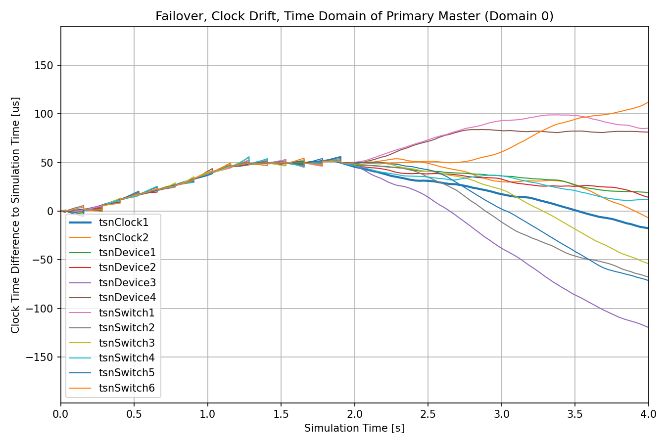
The clocks begin to diverge after the link break at 2s.
The next chart displays the clock drifts in domain 2 (clock time of the hot-standby master node):
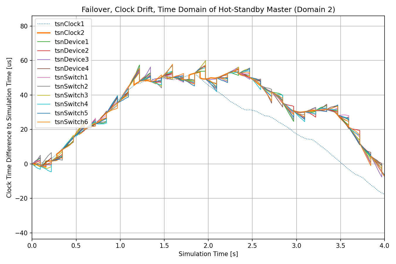
After the link break, the clocks are synchronized with the hot-standby master’s time.
Note
The two charts above are exactly the same as the charts for Time Domain 0 and 2 in the Link Failure of Master Clock section because there is no difference between the two cases in time synchronization and the scheduled link break. The difference is in which one is the active time domain.
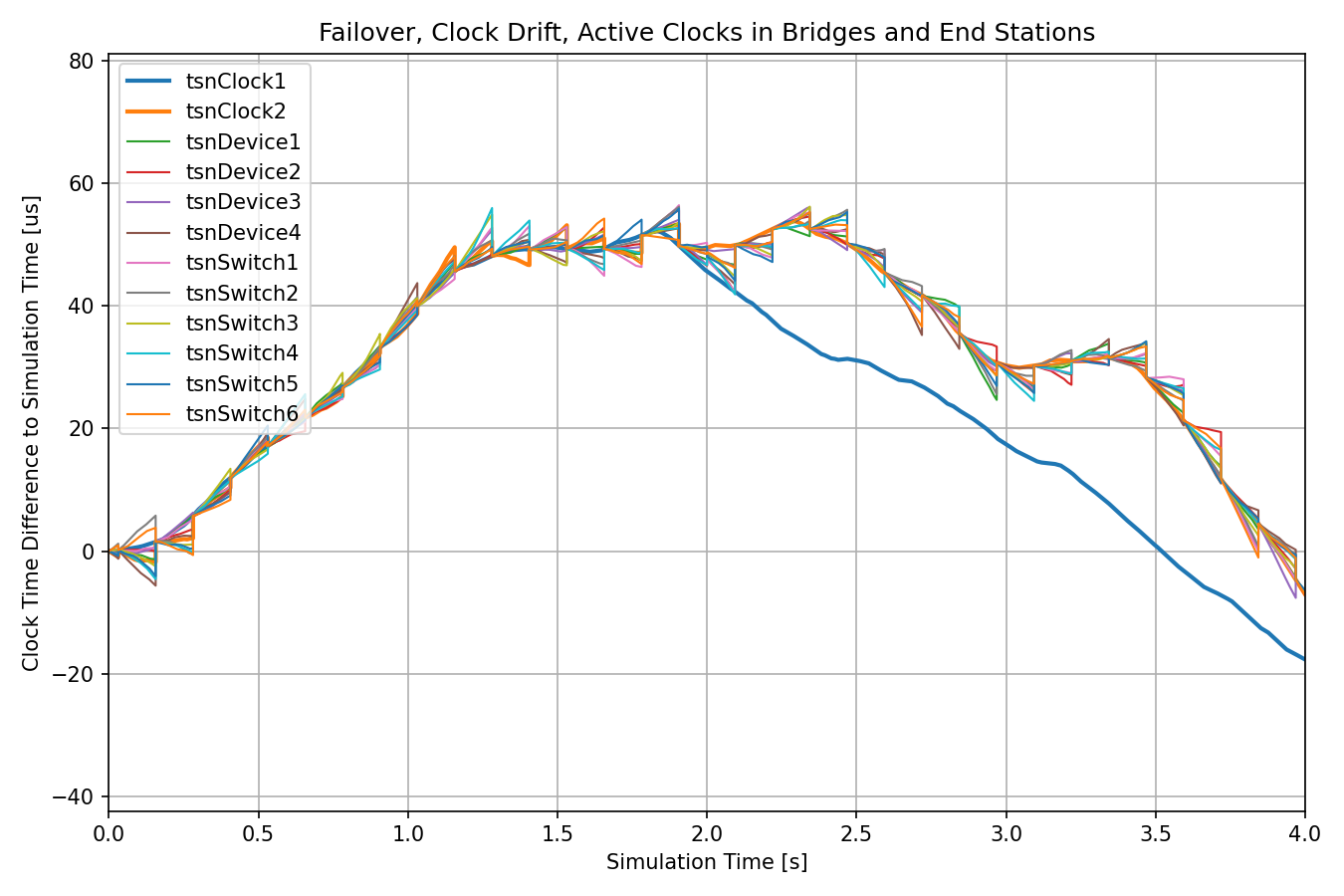
The next chart displays the clock drift of the active clock in all nodes:
The following chart displays the delay:
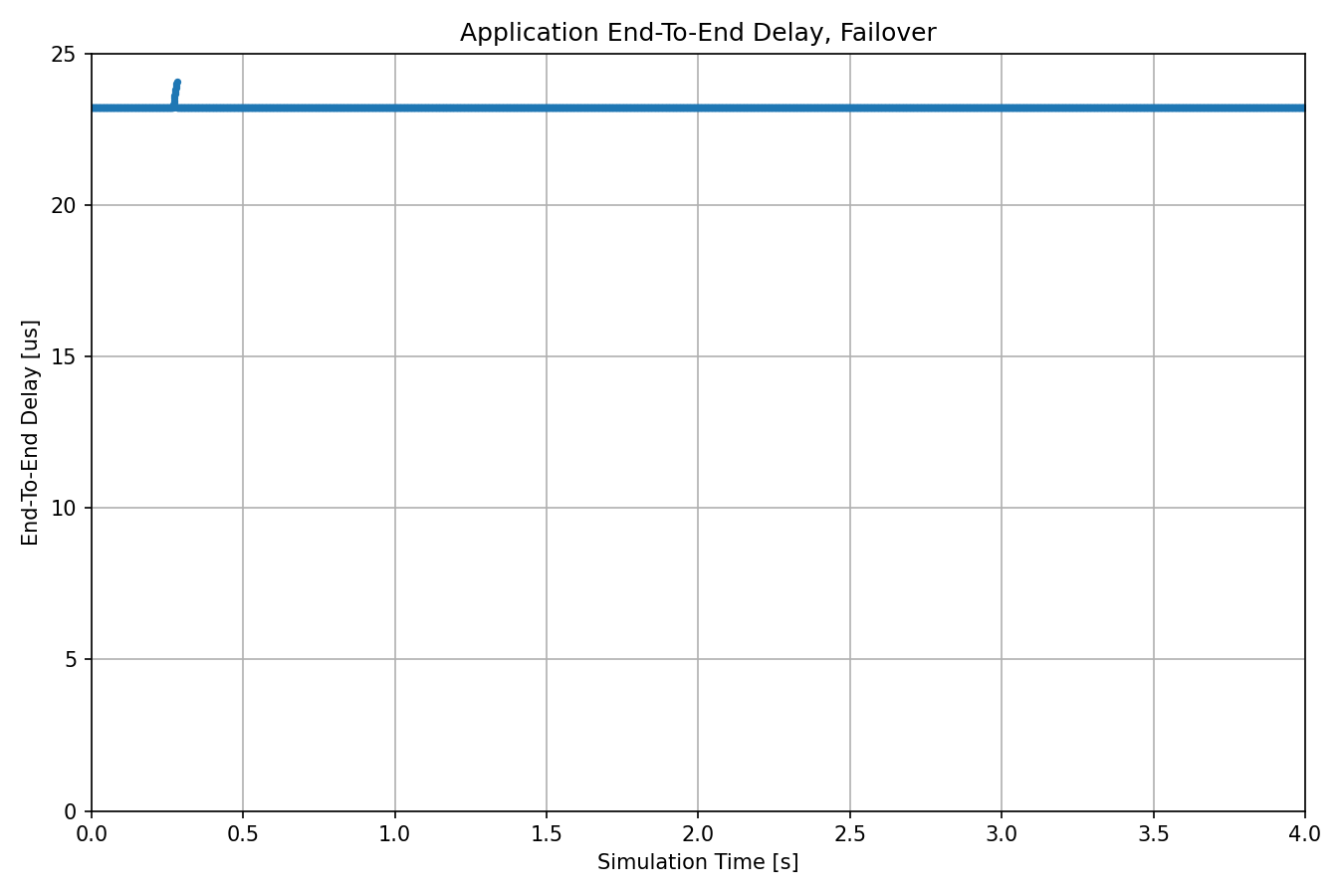
The delay is constant and similar to the delay during normal operation, due to the seamless failover to the hot-standby master node (not even one frame suffers increased delay). For comparison, the next chart displays the delay for the three configurations on individual plots, with the same axis scale:
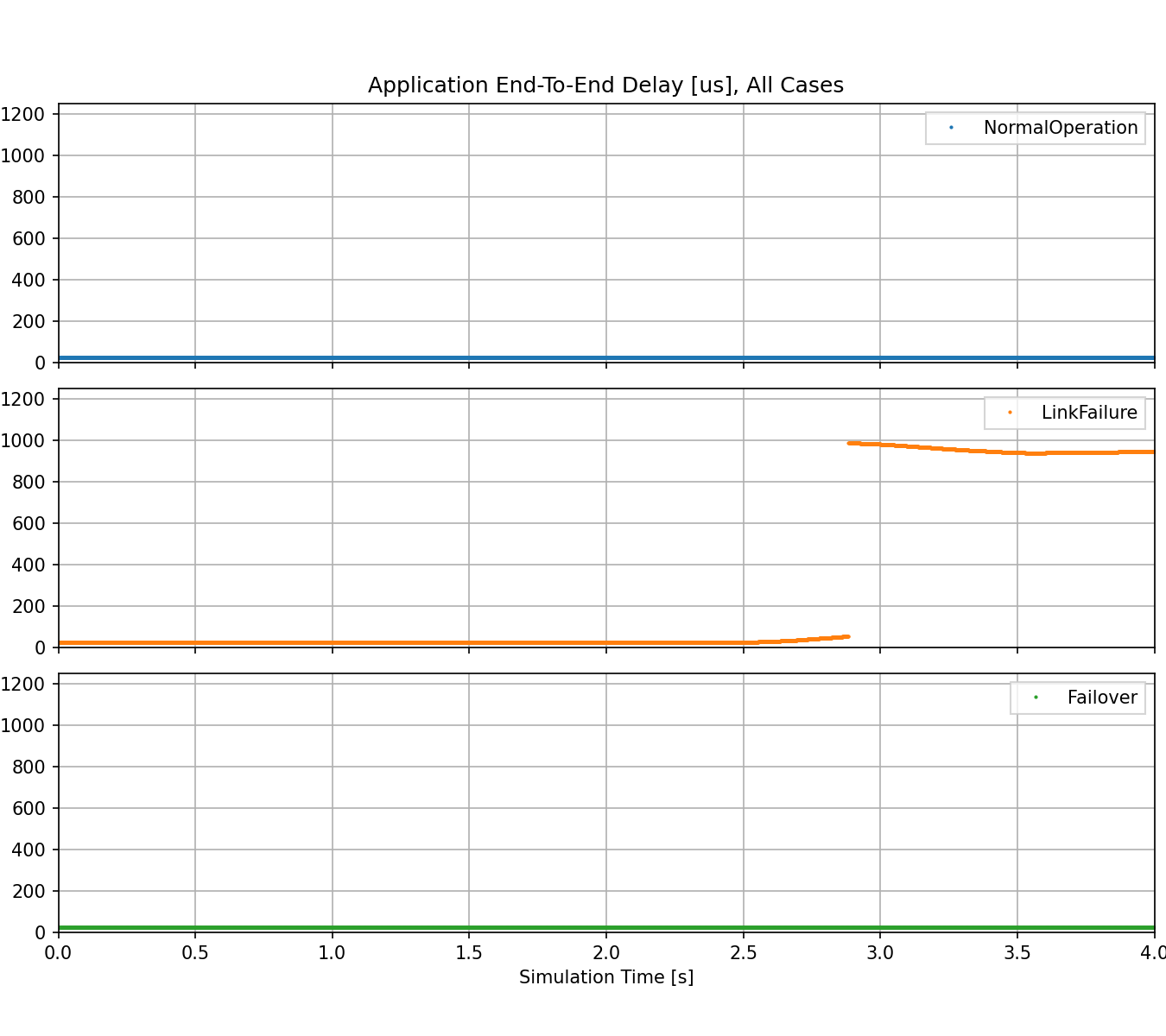
Note
There is a configuration in extras.ini that simulates what happens if the primary master clock comes back online after some time, and all nodes switch back to it. The relevant charts are in Extras.anf.
omnetpp.ini, GptpAndTasShowcase.nedextras.iniTry It Yourself
If you already have INET and OMNeT++ installed, start the IDE by typing
omnetpp, import the INET project into the IDE, then navigate to the
inet/showcases/tsn/combiningfeatures/gptpandtas folder in the Project Explorer. There, you can view
and edit the showcase files, run simulations, and analyze results.
Otherwise, there is an easy way to install INET and OMNeT++ using opp_env, and run the simulation interactively.
Ensure that opp_env is installed on your system, then execute:
$ opp_env run inet-4.6 --init -w inet-workspace --install --build-modes=release --chdir \
   -c 'cd inet-4.6.*/showcases/tsn/combiningfeatures/gptpandtas && inet'
This command creates an inet-workspace directory, installs the appropriate
versions of INET and OMNeT++ within it, and launches the inet command in the
showcase directory for interactive simulation.
Alternatively, for a more hands-on experience, you can first set up the workspace and then open an interactive shell:
$ opp_env install --init -w inet-workspace --build-modes=release inet-4.6
$ cd inet-workspace
$ opp_env shell
Inside the shell, start the IDE by typing omnetpp, import the INET project,
then start exploring.
Discussion
Use this page in the GitHub issue tracker for commenting on this showcase.