Step 12. Mixing different kinds of autorouting
Goals
Sometimes it is best to configure different parts of a network according to different metrics. This step demonstrates using the hop count and error rate metrics in a mixed wired/wireless network.
The model
This step uses the ConfiguratorE network, defined in
ConfiguratorE.ned. The network
looks like this:
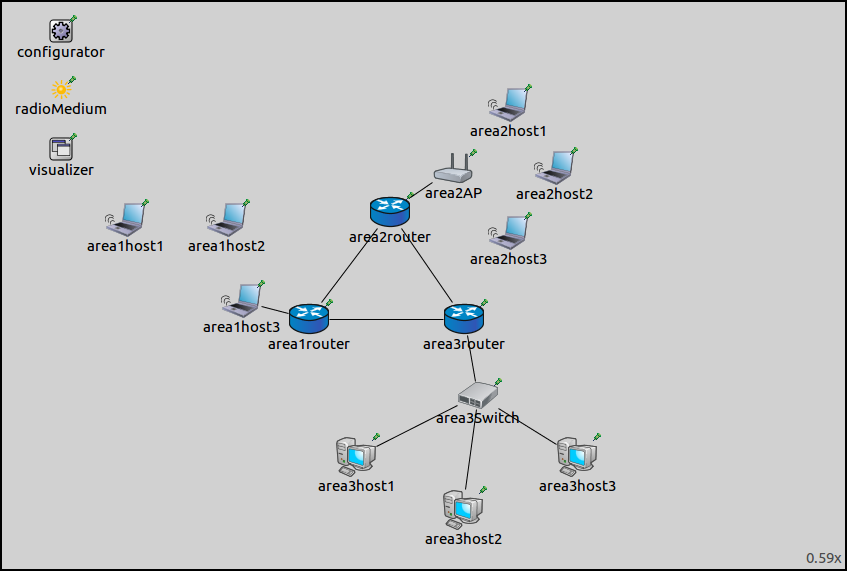
The core of the network is composed of three routers connected to each other, each belonging to an area. There are three areas, each containing a number of hosts, connected to the area router.
Area1 is composed of three
WirelessHosts, one of which is connected to the router with a wired connection.Area2 has an AccessPoint and three
WirelessHosts.Area3 has three
StandardHostsconnected to the router via a switch.
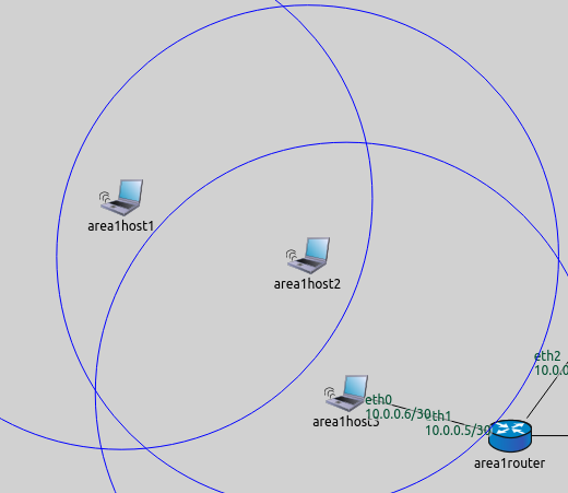
There is no access point in area 1; the hosts form an ad-hoc wireless
network. They connect to the rest of the network through area1host3,
which has a wired connection to the router. However, area1host3 is
not in the communication range of area1host1 (illustrated on the
image below.) Thus, area1host2 needs to be configured to forward
area1host1’s packets to area1host3. The error rate metric,
rather than hop count, is best suited to configure routes in this LAN.
Routes in the rest of the network can be configured properly based on
the hop count metric.

The configuration for this step in omnetpp.ini is the following:
[Config Step12]
network = ConfiguratorE
description = "Mixing different kinds of autorouting"

# Configurator settings
*.configurator.config = xmldoc("step12.xml")
*.configurator.optimizeRoutes = false             #! TODO! különben nem működik -> ezért kell

# Wireless node settings
*.*.wlan[*].bitrate = 54Mbps
*.*.wlan[*].radio.transmitter.power = 1mW
*.area1host*.forwarding = true
*.area1*.wlan[*].mgmt.typename = "Ieee80211MgmtAdhoc"
*.area1*.wlan[*].agent.typename = ""

# pingApp settings
*.area1host1.numApps = 1
*.area1host1.app[0].typename = "PingApp"
*.area1host1.app[*].destAddr = "area2host1"

# Visualizer settings
*.visualizer.mediumVisualizer.displayCommunicationRanges = true
*.visualizer.routingTableVisualizer.displayRoutingTables = true
*.visualizer.routingTableVisualizer.displayRoutesIndividually = false
*.visualizer.routingTableVisualizer.displayLabels = false
*.visualizer.routingTableVisualizer.lineShift = 0
*.visualizer.routingTableVisualizer.destinationFilter = "*"
Explanation:
For hosts in area 1 to operate in ad-hoc mode, IP forwarding is turned on, and their management modules are set to ad-hoc management.
area1host1is configured to pingarea2host1, which is on the other side of the network.Routes to all hosts and communication ranges are visualized.
The XML configuration in step12.xml is the following:
<config>
    <interface hosts="area1*" address="10.x.x.x" netmask="255.x.x.x" add-default-route="false"/>
    <interface hosts="**" address="10.x.x.x" netmask="255.x.x.x"/>
    <autoroute metric="hopCount" sourceHosts="*.area2host* *router area3host*"/>
    <autoroute metric="errorRate" sourceHosts="*.area1host*"/>
</config>
To have routes from every node to every other node, all nodes must be covered by an autoroute element. The XML configuration contains two autoroute elements. Routing tables of hosts in area 1 are configured according to the error rate metric, while all others according to hop count.
The global addStaticRoutes, addDefaultRoutes and
addSubnetRoutes parameters can also be specified per interface, with
attributes of the <interface> element. The attribute names are
add-static-route, add-default-route and add-subnet-route,
and they are all booleans with true as default value. The global and
per-interface settings are in a logical AND relationship, so both have
to be true to take effect.
The default route assumes there is one gateway, and all nodes on the
link can reach it directly. This is not the case for area 1, because
area1host1 is out of range of the gateway host. The
add-default-route parameter is set to false for the area 1 hosts.
Results
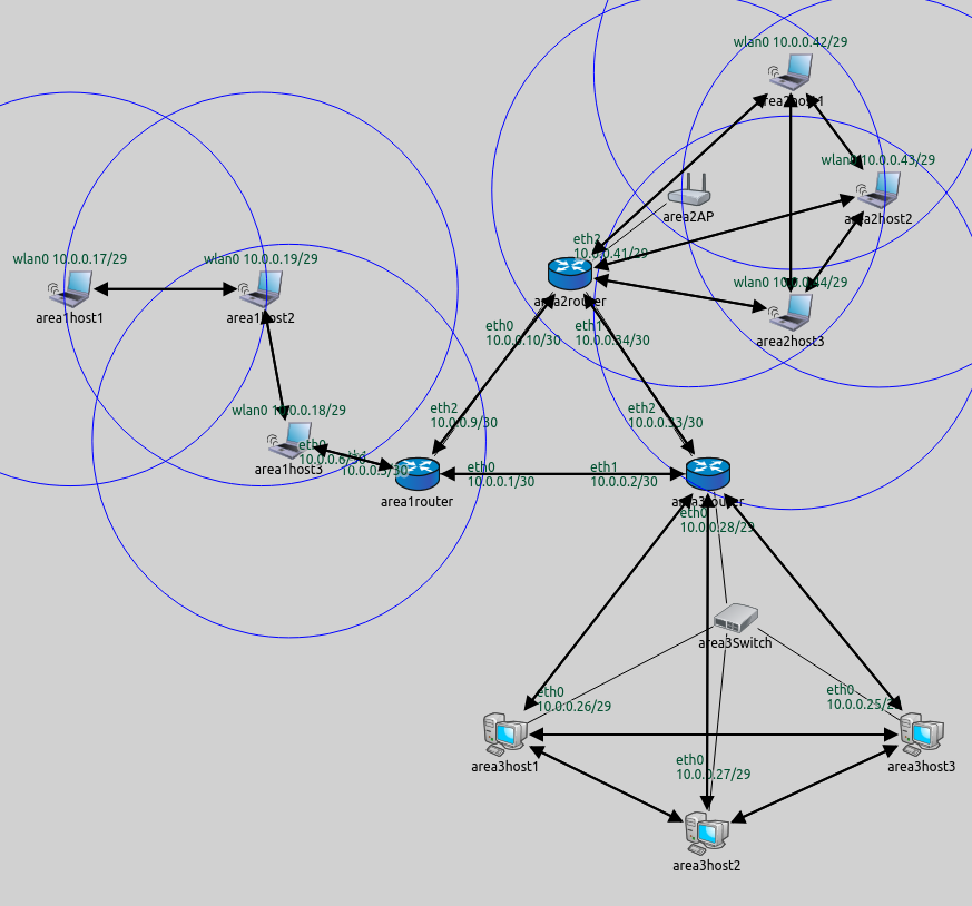
The routes are visualized on the following image.
As intended, area1host1 connects to the network via area1host2.
The routing table of area1host1 is as follows:
Node ConfiguratorF.area1host1
-- Routing table --
Destination      Netmask          Gateway          Iface             Metric
10.0.0.1         255.255.255.255  10.0.0.19        wlan0 (10.0.0.17)      0
10.0.0.2         255.255.255.255  10.0.0.19        wlan0 (10.0.0.17)      0
10.0.0.5         255.255.255.255  10.0.0.19        wlan0 (10.0.0.17)      0
10.0.0.6         255.255.255.255  10.0.0.19        wlan0 (10.0.0.17)      0
10.0.0.9         255.255.255.255  10.0.0.19        wlan0 (10.0.0.17)      0
10.0.0.10        255.255.255.255  10.0.0.19        wlan0 (10.0.0.17)      0
10.0.0.18        255.255.255.255  10.0.0.19        wlan0 (10.0.0.17)      0
10.0.0.28        255.255.255.255  10.0.0.19        wlan0 (10.0.0.17)      0
10.0.0.33        255.255.255.255  10.0.0.19        wlan0 (10.0.0.17)      0
10.0.0.34        255.255.255.255  10.0.0.19        wlan0 (10.0.0.17)      0
10.0.0.41        255.255.255.255  10.0.0.19        wlan0 (10.0.0.17)      0
10.0.0.16        255.255.255.248  *                wlan0 (10.0.0.17)      0
10.0.0.24        255.255.255.248  10.0.0.19        wlan0 (10.0.0.17)      0
10.0.0.40        255.255.255.248  10.0.0.19        wlan0 (10.0.0.17)      0
The gateway is 10.0.0.19 (area1host2) in all rules, except in the
one where it is *. That rule is for reaching the other hosts in the
LAN directly. This doesn’t seem to be according to the error rate
metric, but the * rule matches destinations 10.0.0.18 and 10.0.0.19
only. Since 10.0.0.18 is covered by a previous rule, this one is
actually for reaching 10.0.0.19 directly.
The following video shows area1host1 pinging area2host1:
Sources: omnetpp.ini,
ConfiguratorE.ned

