Step 1. Pinging after OSPF convergence
Goals
The goal of this step is to demonstrate basic OSPF operation in a single-area network and verify that hosts can communicate after OSPF convergence.
OSPF (Open Shortest Path First) is a link-state routing protocol. Routers running OSPF exchange Link State Advertisements (LSAs) to build a complete topology database (LSDB). Each router then runs the SPF (Shortest Path First) algorithm on this database to compute the shortest paths to all destinations and populate its routing table.
This step shows OSPF operating in a single area (Area 0.0.0.0), with routers establishing adjacencies, exchanging LSAs, building their LSDBs, and computing routes. After convergence, hosts can ping each other across the network using the OSPF-computed routes.
Configuration
This step uses the OspfNetwork topology with five routers (R1-R5) and nine hosts (host0-host8) connected via switches and point-to-point links.
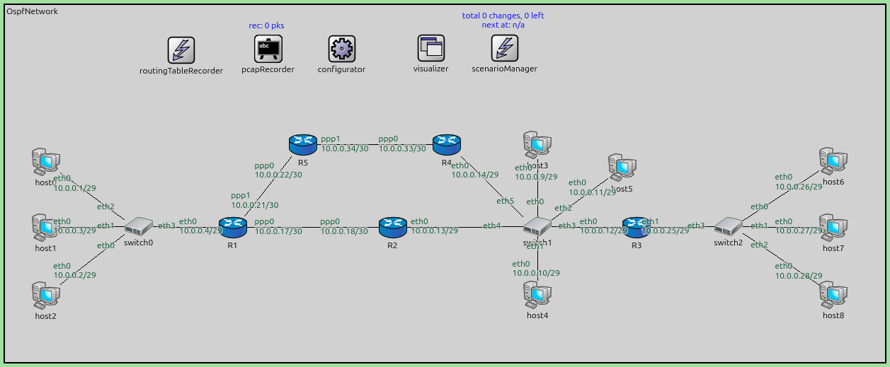
network OspfNetwork
{
    @display("bgb=2099.7375,852.525");

    types:
        channel PppLink100M extends DatarateChannel
        {
            delay = 5us;
            datarate = 100Mbps;
        }

        channel PppLink10M extends DatarateChannel
        {
            delay = 5us;
            datarate = 10Mbps;
        }

    submodules:
        configurator: Ipv4NetworkConfigurator {
            @display("p=804,105");
        }
        visualizer: IntegratedMultiCanvasVisualizer {
            @display("p=1017,103");
        }
        routingTableRecorder: RoutingTableRecorder {
            @display("p=421,108");
        }
        pcapRecorder: PcapRecorder {
            @display("p=628,105");
        }
        scenarioManager: ScenarioManager {
            @display("p=1193,103");
        }
        host0: StandardHost {
            @display("p=97.81249,375.59998");
        }
        host1: StandardHost {
            @display("p=97.81249,532.1");
        }
        host2: StandardHost {
            @display("p=97.81249,694.46875");
        }
        host3: StandardHost {
            @display("p=1271.5625,334.51874");
        }
        R1: Router {
            @display("p=543.83746,532.1");
        }
        R3: Router {
            @display("p=1508.2687,532.1");
        }
        R2: Router {
            @display("p=925.3062,532.1");
        }
        host4: StandardHost {
            @display("p=1271.5625,692.51245");
        }
        host5: StandardHost {
            @display("p=1473.0562,389.29373");
        }
        host6: StandardHost {
            @display("p=1977.7687,373.64374");
        }
        host7: StandardHost {
            @display("p=1977.7687,532.1");
        }
        host8: StandardHost {
            @display("p=1977.7687,692.51245");
        }
        switch0: EthernetSwitch {
            @display("p=318.86874,530.14374");
        }
        switch2: EthernetSwitch {
            @display("p=1727.3687,530.14374");
        }
        switch1: EthernetSwitch {
            @display("p=1271.5625,530.14374");
        }
        R4: Router {
            @display("p=1054.4187,334.51874");
        }
        R5: Router {
            @display("p=712.07495,334.51874");
        }

    connections:
        host2.ethg++ <--> Eth100M <--> switch0.ethg++;
        host1.ethg++ <--> Eth100M <--> switch0.ethg++;
        host0.ethg++ <--> Eth100M <--> switch0.ethg++;
        switch0.ethg++ <--> Eth100M <--> R1.ethg++;

        switch1.ethg++ <--> Eth100M <--> host3.ethg++;
        switch1.ethg++ <--> Eth100M <--> host4.ethg++;
        switch1.ethg++ <--> Eth100M <--> host5.ethg++;
        switch1.ethg++ <--> Eth100M <--> R3.ethg++;

        switch2.ethg++ <--> Eth100M <--> host6.ethg++;
        switch2.ethg++ <--> Eth100M <--> host7.ethg++;
        switch2.ethg++ <--> Eth100M <--> host8.ethg++;

        R3.ethg++ <--> Eth100M <--> switch2.ethg++;
        R1.pppg++ <--> PppLink10M <--> R2.pppg++;
        R2.ethg++ <--> Eth10M <--> switch1.ethg++;
        R1.pppg++ <--> PppLink100M <--> R5.pppg++;
        R5.pppg++ <--> PppLink100M <--> R4.pppg++;
        R4.ethg++ <--> Eth100M <--> switch1.ethg++;
}
The configuration in omnetpp.ini is the following:
[Config Step1]
description = "Pinging after OSPF convergence"
network = OspfNetwork

*.configurator.config = xml("<config> \
                                <interface hosts='**' address='10.x.x.x' netmask='255.x.x.x'/> \
                                <route hosts='host*' destination='*' netmask='0.0.0.0' interface='eth0' /> \
                             </config>")

# application parameters
*.host0.numApps = 1
*.host0.app[0].typename = "PingApp"
*.host0.app[0].destAddr = "host6"
*.host0.app[0].startTime = 60s
Results
When the simulation starts:
All OSPF routers discover their neighbors and establish adjacencies.
Routers exchange Hello packets, then Database Description packets, Link State Request/Update packets to synchronize their LSDBs.
Each router runs the SPF algorithm to compute lowest cost paths (running Dijkstra’s weighted shortest path algorithm) to all subnetworks in the area.
The routing tables are populated with OSPF-learned routes. For example, R1 learns routes to the 10.0.0.24/29 network (behind R3) via the path through R2 and R5->R4.
The R5->R4 path turns out to be higher hop-count but lower cost than the R2 path due to cost associated with link datarates.
At t=60s, host0 begins pinging host6. The ping succeeds because OSPF has computed valid routes between all subnetworks.
Sources:
omnetpp.ini,
OspfNetwork.ned
Discussion
Use this page in the GitHub issue tracker for commenting on this tutorial.