Step 11. Multi-hop E-BGP
Goals
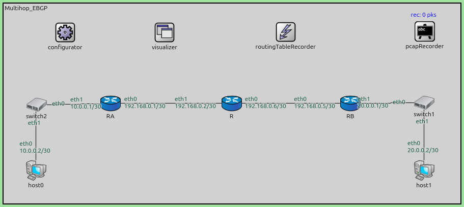
Step 11 introduces Multi-hop E-BGP. By default, External BGP (E-BGP) assumes that peers are directly connected (on the same physical link) and uses an IP Time-To-Live (TTL) of 1 for its BGP packets. If border routers are separated by one or more intermediate routers, the default E-BGP session closure will fail.
This scenario (Multihop_EBGP.ned) demonstrates how to establish an E-BGP
session between two border routers (RA and RB) that are separated by an
intermediate router (R) belonging to a different infrastructure or acting as a
simple forwarder.
Key features demonstrated:
E-BGP Multihop: Using the
ebgpMultihopattribute in the BGP configuration to increase the packet TTL, allowing the BGP session to traverse intermediate hops.Peering Reachability: In a multi-hop setup, peers must know how to reach each other’s IP addresses before BGP can start. This is often achieved through static routes or an IGP.
Transit Routing: Verifying that the intermediate router (R) successfully forwards BGP control traffic and subsequent data traffic between ASes.
Configuration
This step uses the following network:
network Multihop_EBGP
{
    @display("bgb=690,303");

    submodules:
        configurator: Ipv4NetworkConfigurator {
            @display("p=93,44");
        }
        visualizer: IntegratedMultiCanvasVisualizer {
            @display("p=243.2025,43.536247");
        }
        routingTableRecorder: RoutingTableRecorder {
            @display("p=426,43");
        }
        pcapRecorder: PcapRecorder {
            @display("p=636,42");
        }
        RA: Router {
            @display("p=161.33,151.385");
        }
        RB: Router {
            @display("p=523.77,151.385");
        }
        R: Router {
            @display("p=344.76,151.385");
        }

        switch2: EthernetSwitch {
            @display("p=49.725,153.595");
        }
        switch1: EthernetSwitch {
            @display("p=635.375,150.28");
        }
        host0: StandardHost {
            @display("p=49,253");
        }
        host1: StandardHost {
            @display("p=635,253");
        }
    connections:
        RB.ethg++ <--> Eth100M <--> R.ethg++;
        RA.ethg++ <--> Eth100M <--> R.ethg++;
        switch2.ethg++ <--> Eth100M <--> RA.ethg++;
        RB.ethg++ <--> Eth100M <--> switch1.ethg++;
        host1.ethg++ <--> Eth100M <--> switch1.ethg++;
        host0.ethg++ <--> Eth100M <--> switch2.ethg++;
}
The topology is a simple chain: RA <--> R <--> RB.
RA belongs to AS 64520.
RB belongs to AS 64530.
R is an intermediate node.
The omnetpp.ini configuration sets up static routes so RA and RB can reach each other’s peering addresses:
[Config Step11]
description = "Multi-hop E-BGP"
network = Multihop_EBGP
*.routingTableRecorder.logfile = "step11.rt"

*.pcapRecorder.pcapFile = "step11.pcap"

*.configurator.config = xml("<config> \
                                <interface among='RA host0' address='10.0.x.x' netmask='255.x.x.x'/> \
                                <interface among='RB host1' address='20.0.x.x' netmask='255.x.x.x'/> \
                                <interface among='RA R RB' address='192.168.x.x' netmask='255.x.x.x'/> \
                                <route hosts='RA' destination='192.168.0.5' netmask='255.255.255.255' interface='eth0' /> \
                                <route hosts='RB' destination='192.168.0.1' netmask='255.255.255.255' interface='eth0' /> \
                                <route hosts='host*' destination='*' netmask='0.0.0.0' interface='eth0' /> \
                             </config>")

*.RA.hasBgp = true
*.RB.hasBgp = true
*.R*.bgp.bgpConfig = xmldoc("BGPConfig_MultiHopEBGP.xml")
The BGP configuration (BGPConfig_MultiHopEBGP.xml) specifies ebgpMultihop='2' for both neighbors:
    <AS id="64520">
    	<!--router RA-->
        <Router interAddr="10.0.0.1">
            <Network address='10.0.0.0' />
            <Neighbor address='192.168.0.5' ebgpMultihop='2' />
        </Router>
    </AS>

    <AS id="64530">
    	<!--router RB-->
        <Router interAddr="20.0.0.1">
            <Network address='20.0.0.0' />
            <Neighbor address='192.168.0.1' ebgpMultihop='2' />
        </Router>
    </AS>
Results
The simulation results in step11.rt show the successful establishment of the multi-hop session:
Static Convergence: RA and RB use the configured static routes to reach each other via R.
BGP Session Establishment: Because
ebgpMultihop='2'is set, the BGP packets sent by RA can reach RB (and vice-versa) even though they pass through R. The TCP connection is established successfully.Route Exchange:
RA advertises its 10.0.0.0/30 network to RB.
RB advertises its 20.0.0.0/30 network to RA.
Data Reachability: Once BGP converges, hosts behind RA can reach hosts behind RB.
step11.rtconfirms that RA eventually has a BGP route to 20.0.0.0/30 with RB’s address as the next hop.
This step demonstrates a common real-world scenario where border routers might not be physically adjacent, requiring multihop capabilities to form the BGP adjacency.
Sources: Multihop_EBGP.ned,
omnetpp.ini,
BGPConfig_MultiHopEBGP.xml
Discussion
Use this page in the GitHub issue tracker for commenting on this tutorial.