Step 3. BGP Path Attributes
Goals
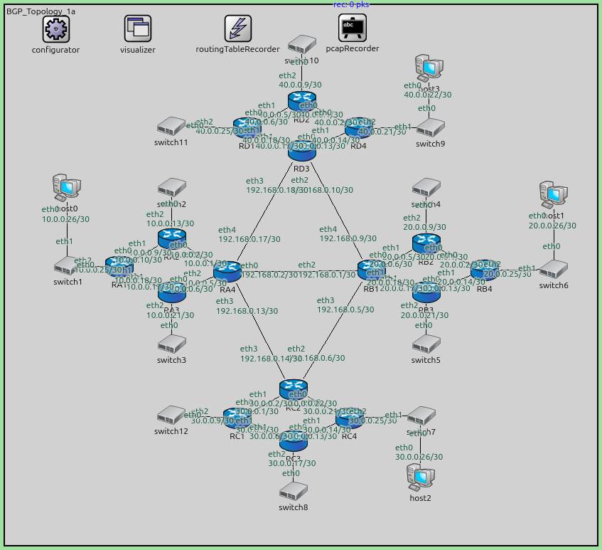
This step explores a more complex multi-AS topology comprising four Autonomous Systems (AS 64500 to AS 64800) with a total of 16 routers. The border routers (RA4, RB1, RC2, and RD3) are interconnected in a full mesh of E-BGP sessions.
The primary objectives are:
Observed path selection based on the
AS_PATHattribute.Verify reachability across multiple ASes using OSPF-to-BGP redistribution.
In this scenario, every border router learns paths to every other AS through
multiple neighbors. BGP selects the best path primarily based on the shortest
AS_PATH length.
Configuration
This step uses the following network:
network BGP_Topology_1a
{
    @display("bgb=1081.6675,985.49");

    submodules:
        configurator: Ipv4NetworkConfigurator {
            @display("p=93,44");
        }
        visualizer: IntegratedMultiCanvasVisualizer {
            @display("p=243.2025,43.536247");
        }
        routingTableRecorder: RoutingTableRecorder {
            @display("p=426,43");
        }
        pcapRecorder: PcapRecorder {
            @display("p=636,42");
        }
        RB2: Router {
            @display("p=770.3949,436.40866");
        }
        RB3: Router {
            @display("p=770.3949,525.4717");
        }
        RB4: Router {
            @display("p=877.2705,485.3933");
        }
        RB1: Router {
            @display("p=670.19904,485.3933");
        }
        RA4: Router {
            @display("p=407.4632,487.6199");
        }
        RA2: Router {
            @display("p=305.04077,427.50238");
        }
        RA3: Router {
            @display("p=305.04077,525.4717");
        }

        RA1: Router {
            @display("p=209.29803,478.7136");
        }
        switch1: EthernetSwitch {
            @display("p=115.78189,476.48703");
        }
        switch2: EthernetSwitch {
            @display("p=305.04077,333.98624");
        }
        switch3: EthernetSwitch {
            @display("p=305.04077,618.9878");
        }
        switch4: EthernetSwitch {
            @display("p=770.3949,333.98624");
        }
        switch5: EthernetSwitch {
            @display("p=770.3949,618.9878");
        }
        switch6: EthernetSwitch {
            @display("p=1004.18524,483.16675");
        }
        host0: StandardHost {
            @display("p=113.55532,333.98624");
        }
        host1: StandardHost {
            @display("p=1004.18524,347.34567");
        }
        RC1: Router {
            @display("p=425.2758,754.8089");
        }
        RC3: Router {
            @display("p=527.69824,797.11383");
        }
        RC4: Router {
            @display("p=630.12067,754.8089");
        }
        switch7: EthernetSwitch {
            @display("p=761.4886,750.3557");
        }
        host2: StandardHost {
            @display("p=760.1975,862.96246");
        }
        switch8: EthernetSwitch {
            @display("p=527.69824,888.4034");
        }
        RC2: Router {
            @display("p=527.69824,703.59766");
        }
        RD2: Router {
            @display("p=542.81,176.545");
        }
        RD3: Router {
            @display("p=542.81,266.135");
        }
        RD4: Router {
            @display("p=646.8925,225.2925");
        }
        switch9: EthernetSwitch {
            @display("p=778.6425,223.97499");
        }
        RD1: Router {
            @display("p=442.68,225.2925");
        }
        switch10: EthernetSwitch {
            @display("p=542.81,72.4625");
        }
        host3: StandardHost {
            @display("p=776.0075,115.939995");
        }
        switch11: EthernetSwitch {
            @display("p=304.3425,221.34");
        }
        switch12: EthernetSwitch {
            @display("p=304.3425,749.6575");
        }
    connections:
        RB2.ethg++ <--> Eth100M <--> RB4.ethg++;
        RB3.ethg++ <--> Eth100M <--> RB4.ethg++;
        RB1.ethg++ <--> Eth100M <--> RB2.ethg++;
        RB1.ethg++ <--> Eth100M <--> RB3.ethg++;
        RB1.ethg++ <--> Eth100M <--> RA4.ethg++;
        RA4.ethg++ <--> Eth100M <--> RA2.ethg++;
        RA3.ethg++ <--> Eth100M <--> RA4.ethg++;
        RA2.ethg++ <--> Eth100M <--> RA1.ethg++;
        RA1.ethg++ <--> Eth100M <--> RA3.ethg++;
        switch1.ethg++ <--> Eth100M <--> RA1.ethg++;
        RA2.ethg++ <--> Eth100M <--> switch2.ethg++;
        RA3.ethg++ <--> Eth100M <--> switch3.ethg++;
        RB2.ethg++ <--> Eth100M <--> switch4.ethg++;
        RB3.ethg++ <--> Eth100M <--> switch5.ethg++;
        switch1.ethg++ <--> Eth100M <--> host0.ethg++;
        switch6.ethg++ <--> Eth100M <--> host1.ethg++;
        RB4.ethg++ <--> Eth100M <--> switch6.ethg++;
        RC2.ethg++ <--> Eth100M <--> RC4.ethg++;
        RC3.ethg++ <--> Eth100M <--> RC4.ethg++;
        RC1.ethg++ <--> Eth100M <--> RC2.ethg++;
        RC1.ethg++ <--> Eth100M <--> RC3.ethg++;
        RC3.ethg++ <--> Eth100M <--> switch8.ethg++;
        switch7.ethg++ <--> Eth100M <--> host2.ethg++;
        RC4.ethg++ <--> Eth100M <--> switch7.ethg++;
        RC2.ethg++ <--> Eth100M <--> RB1.ethg++;
        RC2.ethg++ <--> Eth100M <--> RA4.ethg++;
        RD2.ethg++ <--> Eth100M <--> RD4.ethg++;
        RD3.ethg++ <--> Eth100M <--> RD4.ethg++;
        RD1.ethg++ <--> Eth100M <--> RD2.ethg++;
        RD1.ethg++ <--> Eth100M <--> RD3.ethg++;
        switch9.ethg++ <--> Eth100M <--> host3.ethg++;
        RD4.ethg++ <--> Eth100M <--> switch9.ethg++;
        RB1.ethg++ <--> Eth100M <--> RD3.ethg++;
        RD1.ethg++ <--> Eth100M <--> switch11.ethg++;
        RD2.ethg++ <--> Eth100M <--> switch10.ethg++;
        RC1.ethg++ <--> Eth100M <--> switch12.ethg++;
        RA4.ethg++ <--> Eth100M <--> RD3.ethg++;
}
The configuration in omnetpp.ini is the following:
[Config Step3]
description = "BGP Path Attributes"
network = BGP_Topology_1a
*.routingTableRecorder.logfile = "step3.rt"

*.pcapRecorder.pcapFile = "step3.pcap"

*.configurator.config = xml("<config> \
                                <interface hosts='RA4' names='eth0' address='192.168.x.x' netmask='255.x.x.x'/> \
                                <interface hosts='RB1' names='eth2' address='192.168.x.x' netmask='255.x.x.x'/> \
                                \
                                <interface hosts='RA4' names='eth3' address='192.168.x.x' netmask='255.x.x.x'/> \
                                <interface hosts='RC2' names='eth3' address='192.168.x.x' netmask='255.x.x.x'/> \
                                \
                                <interface hosts='RA4' names='eth4' address='192.168.x.x' netmask='255.x.x.x'/> \
                                <interface hosts='RD3' names='eth3' address='192.168.x.x' netmask='255.x.x.x'/> \
                                \
                                <interface hosts='RB1' names='eth3' address='192.168.x.x' netmask='255.x.x.x'/> \
                                <interface hosts='RC2' names='eth2' address='192.168.x.x' netmask='255.x.x.x'/> \
                                \
                                <interface hosts='RD3' names='eth2' address='192.168.x.x' netmask='255.x.x.x'/> \
                                <interface hosts='RB1' names='eth4' address='192.168.x.x' netmask='255.x.x.x'/> \
                                \
                                <interface among='host0 RA*' address='10.x.x.x' netmask='255.x.x.x'/> \
                                <interface hosts='RA*' address='10.x.x.x' netmask='255.x.x.x'/> \
                                \
                                <interface among='host1 RB*' address='20.x.x.x' netmask='255.x.x.x'/> \
                                <interface hosts='RB*' address='20.x.x.x' netmask='255.x.x.x'/> \
                                \
                                <interface among='host2 RC*' address='30.x.x.x' netmask='255.x.x.x'/> \
                                <interface hosts='RC*' address='30.x.x.x' netmask='255.x.x.x'/> \
                                \
                                <interface among='host3 RD*' address='40.x.x.x' netmask='255.x.x.x'/> \
                                <interface hosts='RD*' address='40.x.x.x' netmask='255.x.x.x'/> \
                                \
                                <route hosts='host*' destination='*' netmask='0.0.0.0' interface='eth0' /> \
                             </config>")

# OSPF configuration
*.R*.hasOspf = true
*.R*.ospf.ospfConfig = xmldoc("OSPFConfig_FullAS.xml")

*.RA4.ipv4.routingTable.routerId = "10.0.0.5"
*.RB1.ipv4.routingTable.routerId = "20.0.0.18"
*.RC2.ipv4.routingTable.routerId = "30.0.0.22"
*.RD3.ipv4.routingTable.routerId = "40.0.0.17"

# BGP configuration
*.RA4.hasBgp = true
*.RB1.hasBgp = true
*.RC2.hasBgp = true
*.RD3.hasBgp = true
*.R*.bgp.bgpConfig = xmldoc("BGPConfig_FullAS.xml")

# enable OSPF redistribution
*.RA4.bgp.redistributeOspf = "O IA"
*.RB1.bgp.redistributeOspf = "O IA"
*.RC2.bgp.redistributeOspf = "O IA"
*.RD3.bgp.redistributeOspf = "O IA"
The BGP configuration:
<?xml version="1.0" encoding="ISO-8859-1"?>
<BGPConfig xmlns:xsi="http://www.w3.org/2001/XMLSchema-instance" xsi:schemaLocation="BGP.xsd">

    <TimerParams>
        <connectRetryTime> 120 </connectRetryTime>
        <holdTime>         180 </holdTime>
        <keepAliveTime>    60  </keepAliveTime>
        <startDelay>       60   </startDelay>
    </TimerParams>

    <AS id="64500">
    	<!--router RA4-->
        <Router interAddr="10.0.0.1" />
    </AS>

    <AS id="64600">
    	<!--router RB1-->
        <Router interAddr="20.0.0.6" />
    </AS>

    <AS id="64700">
    	<!--router RC2-->
        <Router interAddr="30.0.0.2" />
    </AS>

    <AS id="64800">
    	<!--router RD3-->
        <Router interAddr="40.0.0.13" />
    </AS>

    <!--bi-directional E-BGP session between RA4 and RB1-->
    <Session id="1">
        <Router exterAddr="192.168.0.2"/>
        <Router exterAddr="192.168.0.1"/>
    </Session>

    <!--bi-directional E-BGP session between RA4 and RC2-->
    <Session id="2">
        <Router exterAddr="192.168.0.13"/>
        <Router exterAddr="192.168.0.14"/>
    </Session>

    <!--bi-directional E-BGP session between RA4 and RD3-->
    <Session id="3">
        <Router exterAddr="192.168.0.17"/>
        <Router exterAddr="192.168.0.18"/>
    </Session>

    <!--bi-directional E-BGP session between RB1 and RC2-->
    <Session id="4">
        <Router exterAddr="192.168.0.5"/>
        <Router exterAddr="192.168.0.6"/>
    </Session>

    <!--bi-directional E-BGP session between RB1 and RD3-->
    <Session id="5">
        <Router exterAddr="192.168.0.9"/>
        <Router exterAddr="192.168.0.10"/>
    </Session>

</BGPConfig>
Results
The simulation begins with OSPF convergence within each AS. At 60 seconds, the BGP sessions are initiated.
Because the border routers are fully meshed, each router has a direct path to every other AS (distance 1) and several indirect paths (distance 2 through other border routers).
Looking at the routing tables (step3.rt), we can observe:
Border routers prefer the direct connection because it has the shortest
AS_PATH.For example, RA4 will install RD’s networks (40.0.0.0/30 subnets) with a next hop of RD3 (via the RA4-RD3 link), ignoring the longer paths offered by RB1 or RC2.
Due to redistribution, full reachability is achieved between all subnets in the simulation. You can verify this by checking that internal routers (e.g., RA1) eventually populate their tables with routes to the other ASes via their respective border routers.
Sources: BGP_Topology_1a.ned,
omnetpp.ini,
OSPFConfig_FullAS.xml,
BGPConfig_FullAS.xml
Discussion
Use this page in the GitHub issue tracker for commenting on this tutorial.