Step 10. Network Topology Changes
Goals
The goal of this step is to examine how OSPF reacts to network topology changes.
OSPF routers monitor the state of their links. When a link state changes (e.g., up/down), the router generates a new LSA and floods it throughout the area. Other routers receive the update, update their LSDBs, and run the SPF algorithm to calculate new routes.
Configuration
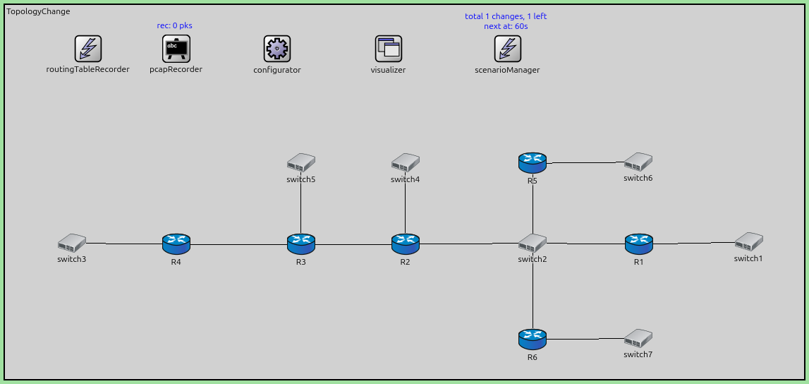
This step uses the TopologyChange network. The OSPF configuration in
ASConfig_tp_priority.xml assigns different priorities to the routers connected to
the central switch (Switch2) to deterministically select the DR and BDR.
R1: Priority 10 (DR)
R5: Priority 9 (BDR)
R2, R6: Priority 1 (DROthers)
The simulation script disconnects the link between R4 and Switch3 at t=60s.
network TopologyChange
{
    @display("bgb=1914.2025,894.73376");

    types:
        channel PppLink100M extends DatarateChannel
        {
            delay = 5us;
            datarate = 100Mbps;
        }

        channel PppLink10M extends DatarateChannel
        {
            delay = 5us;
            datarate = 10Mbps;
        }

    submodules:
        configurator: Ipv4NetworkConfigurator {
            @display("p=652.46,105.545");
        }
        visualizer: IntegratedCanvasVisualizer {
            @display("p=918.72125,105.545");
        }
        routingTableRecorder: RoutingTableRecorder {
            @display("p=199,105");
        }
        pcapRecorder: PcapRecorder {
            @display("p=410,105");
        }
        scenarioManager: ScenarioManager {
            @display("p=1204.1725,105.545");
        }
        R2: Router {
            @display("p=959.4937,573.0675");
        }
        switch3: EthernetSwitch {
            @display("p=160.35374,570.4387");
        }
        R4: Router {
            @display("p=410.085,573.0675");
        }
        R3: Router {
            @display("p=709.7625,573.0675");
        }

        switch2: EthernetSwitch {
            @display("p=1264.4287,570.4387");
        }
        switch5: EthernetSwitch {
            @display("p=709.7625,378.54");
        }
        R1: Router {
            @display("p=1519.4175,573.0675");
        }
        switch4: EthernetSwitch {
            @display("p=959.4937,378.54");
        }
        switch1: EthernetSwitch {
            @display("p=1782.2925,567.81");
        }
        R5: Router {
            @display("p=1264.1412,379.0025");
        }
        R6: Router {
            @display("p=1264.1412,801.1825");
        }
        switch6: EthernetSwitch {
            @display("p=1517.6176,376.4075");
        }
        switch7: EthernetSwitch {
            @display("p=1517.6176,798.3675");
        }
    connections:
        R2.pppg++ <--> PppLink100M <--> R3.pppg++;
        R3.pppg++ <--> PppLink100M <--> R4.pppg++;
        R4.ethg++ <--> Eth100M <--> switch3.ethg++;
        R3.ethg++ <--> Eth100M <--> switch5.ethg++;
        R2.ethg++ <--> Eth100M <--> switch2.ethg++;
        R1.ethg++ <--> Eth100M <--> switch2.ethg++;
        switch4.ethg++ <--> Eth100M <--> R2.ethg++;
        switch1.ethg++ <--> Eth100M <--> R1.ethg++;
        switch2.ethg++ <--> Eth100M <--> R5.ethg++;
        R6.ethg++ <--> Eth100M <--> switch2.ethg++;
        switch6.ethg++ <--> Eth100M <--> R5.ethg++;
        switch7.ethg++ <--> Eth100M <--> R6.ethg++;
}
The configuration in omnetpp.ini is the following:
[Config Step10]
description = "Network Topology Changes"
network = TopologyChange

*.R*.ospf.ospfConfig = xmldoc("ASConfig_tp_priority.xml")

*.visualizer.routingTableVisualizer.displayRoutingTables = true
*.visualizer.routingTableVisualizer.destinationFilter = "*"
*.visualizer.routingTableVisualizer.nodeFilter = "R*"

*.*.hasStatus = true
*.scenarioManager.script = xml("<scenario> \
                                    <disconnect t='60' src-module='R4' dest-module='switch3' /> \
                                </scenario>")


# application parameters
*.R3.numApps = 1
*.R3.app[0].typename = "PingApp"
*.R3.app[0].destAddr = "R1"
*.R3.app[0].startTime = 60s
The OSPF configuration:
<?xml version="1.0"?>
<OSPFASConfig xmlns:xsi="http://www.w3.org/2001/XMLSchema-instance" xsi:schemaLocation="OSPF.xsd">

  <Router name="R1" RFC1583Compatible="true">
    <BroadcastInterface ifName="eth0" interfaceOutputCost='0' routerPriority="10" />
    <BroadcastInterface ifName="eth1" interfaceOutputCost='0' />
  </Router>

  <Router name="R5" RFC1583Compatible="true">
    <BroadcastInterface ifName="eth0" interfaceOutputCost='0' routerPriority="9" />
    <BroadcastInterface ifName="eth1" interfaceOutputCost='0' />
  </Router>

  <Router name="**" RFC1583Compatible="true">
     <BroadcastInterface ifName='eth[*]' areaID='0.0.0.0' interfaceOutputCost='0' />
     <PointToPointInterface ifName='ppp[*]' areaID='0.0.0.0' interfaceOutputCost='0' />
  </Router>

</OSPFASConfig>
Results
When the link between R4 and Switch3 breaks at t=60s:
R4 detects the link down event.
R4 generates a new Router LSA that excludes the link to Switch3’s network.
R4 floods this new LSA to its neighbors (R3).
The LSA propagates through the network (R3 → R2 → Switch2 → others).
All routers update their LSDB and remove the route to the network that was behind Switch3 (if it’s no longer reachable).
This demonstrates the basic mechanism of LSA flooding and database synchronization upon topology change.
Sources:
omnetpp.ini,
TopologyChange.ned,
ASConfig_tp_priority.xml
Discussion
Use this page in the GitHub issue tracker for commenting on this tutorial.