Step 3. Root Bridge Election by Priority
Goals
This step shows how to control which switch becomes the root bridge by configuring bridge priorities, instead of relying on MAC address ordering.
Configuration
The configuration extends Step2 with a single extra parameter:
[Config Step3]
description = "Root bridge election by bridge priority"
extends = Step2

# switch3 becomes root due to lower priority (default is 32768)
**.switch3.**.bridgePriority = 1
Setting bridgePriority = 1 on switch3 gives it a bridge ID of
1:AAAAAA000003, which is lower than all other switches (whose bridge IDs
are 32768:AAAAAA0000xx). Therefore switch3 wins the root election
regardless of its MAC address.
The bridge ID is an 8-byte value. The first two bytes encode the bridge priority; the remaining six bytes are the switch’s MAC address. When comparing bridge IDs, the priority field is compared first, so a switch with a lower priority value always wins the root election, regardless of its MAC address. This allows network administrators to explicitly control root bridge placement.
The bridge priority can be set per-switch using the **.switchN.**.bridgePriority
parameter, or configured across multiple switches using L2NetworkConfigurator.
The default value is 32768.
Note
Per IEEE 802.1D, valid bridge priority values are multiples of 4096 from 0
to 61440 (the priority occupies the upper 4 bits of the 2-byte Bridge ID
field, while the lower 12 bits are reserved for the VLAN System ID
Extension). INET does not enforce this constraint, so any integer value is
accepted by the bridgePriority parameter.
Root bridge placement matters because it determines the shape of the spanning tree, and therefore the paths that traffic follows. A poorly placed root — for example, at the edge of the network — can result in suboptimal, unnecessarily long paths. In practice, the root bridge should be a high-capacity, centrally located switch.
Results
With switch3 as root, the spanning tree is rooted at a different location
compared to Step 2. All root ports now point toward switch3 instead of
switch1, and the set of blocked ports changes accordingly to create the
new loop-free tree.
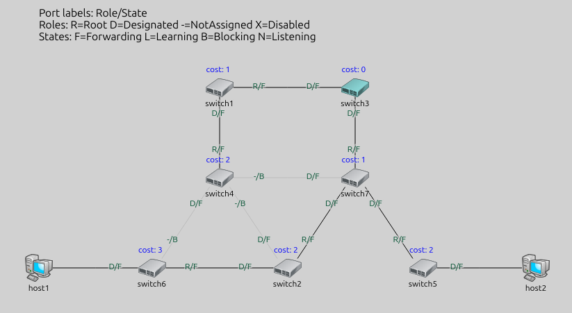
Comparing the two figures (Step 2 vs Step 3) illustrates how root bridge
placement determines the shape of the entire spanning tree. The same physical
topology produces a different logical tree depending on which switch is root.
In Step 2, with switch1 as root (located at the top-left), several hosts
reach the root via longer paths. With switch3 as root (more centrally
located), the tree may offer shorter average path lengths.
Traffic from host2 to host1 still succeeds after convergence, but
follows a different path through the network.
Sources:
omnetpp.ini,
StpTutorial.ned
Discussion
Use this page in the GitHub issue tracker for commenting on this tutorial.