Step 2. Basic STP Operation
Goals
This step demonstrates how the Spanning Tree Protocol (STP) builds a loop-free tree topology from a meshed Ethernet network. We will observe the root bridge election, port role assignment, and which links are blocked to break the loops.
The Network
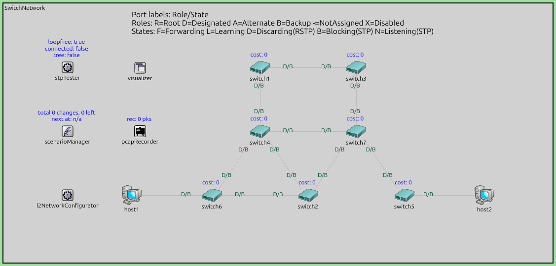
The simulation uses the SwitchNetwork network, which contains seven Ethernet
switches (switch1–switch7) interconnected with redundant links, and two
hosts (host1 and host2) attached to switch6 and switch5
respectively.
About STP
The Spanning Tree Protocol (STP, IEEE 802.1D-1998) eliminates loops by computing a spanning tree of the network — a subset of links that connects all switches without forming any cycles. In graph theory, a spanning tree of a connected graph is a tree that includes every node but only enough edges to keep it connected (exactly N−1 edges for N nodes). Ports on links that are not part of the spanning tree are placed in a blocking state, effectively deactivating those links for data traffic while keeping them available as backups.
STP achieves this through a distributed algorithm. Switches exchange Bridge Protocol Data Units (BPDUs) to share topology information and collectively agree on the tree structure. The algorithm works in the following phases:
1. Root bridge election. All switches start by assuming they are the root. Each switch sends BPDUs containing its own bridge ID — a value composed of a configurable bridge priority (default 32768) and the switch’s MAC address. When a switch receives a BPDU with a lower bridge ID than its own, it accepts the sender’s root claim and stops claiming to be root itself. Eventually, the switch with the numerically lowest bridge ID wins the election and becomes the root bridge. The root bridge is the root of the spanning tree; all paths in the tree lead toward it.
2. Root port selection. Each non-root switch must determine which of its ports provides the best (lowest-cost) path toward the root bridge. STP assigns a path cost to each port based on its link speed (e.g. 4 for 1 Gbps in the revised cost table, or 19 for 100 Mbps in the original). Each BPDU carries a root path cost field — the total cost from the sending switch to the root. When a switch receives a BPDU, it adds the receiving port’s own cost to the advertised root path cost. The port with the lowest total cost to the root becomes the switch’s root port. Ties are broken by lowest upstream bridge ID, then by lowest upstream port ID.
3. Designated port selection. For each network segment (link between two switches), one port must be elected as the designated port — the port responsible for forwarding frames toward the root on that segment. The switch that can offer the lowest root path cost on that segment wins. Ties are broken by bridge ID, then port ID. The root bridge’s ports are always designated (cost = 0).
4. Blocking redundant ports. Any port that is neither a root port nor a designated port is placed in blocking state — it does not forward data frames, breaking the loop. These blocked ports continue to receive BPDUs so they can react if the topology changes.
In INET, STP is implemented by the Stp module, which is enabled per
switch via the hasStp = true and spanningTreeProtocol = "Stp" parameters.
Configuration
[Config Step2]
description = "Basic STP operation - root elected by MAC"
network = StpSwitchNetwork
sim-time-limit = 100s

**.hasStp = true
**.spanningTreeProtocol = "Stp"

**.switch1.**.address = "AAAAAA000001"
**.switch2.**.address = "AAAAAA000002"
**.switch3.**.address = "AAAAAA000003"
**.switch4.**.address = "AAAAAA000004"
**.switch5.**.address = "AAAAAA000005"
**.switch6.**.address = "AAAAAA000006"
**.switch7.**.address = "AAAAAA000007"

**.host2.cli.destAddress = "host1"
**.host2.cli.startTime = 60s
The MAC addresses are fixed (AAAAAA000001 … AAAAAA000007) so that
switch1 (lowest MAC) is always elected root. The visualize = true
parameter colors blocked links gray and active (forwarding) links black, and
highlights the root bridge in cyan. Port roles and states are also displayed
as labels on each switch interface.
Traffic from host2 to host1 starts at t=60s, after STP has converged.
Observing the Simulation
When running the simulation in Qtenv, several visual cues help you follow the STP algorithm:
Packet names reflect the BPDU type. Periodic hello BPDUs are named
stp-hello; topology change notifications arestp-tcn.Port labels on each switch interface show the port role and state as a short code, e.g.
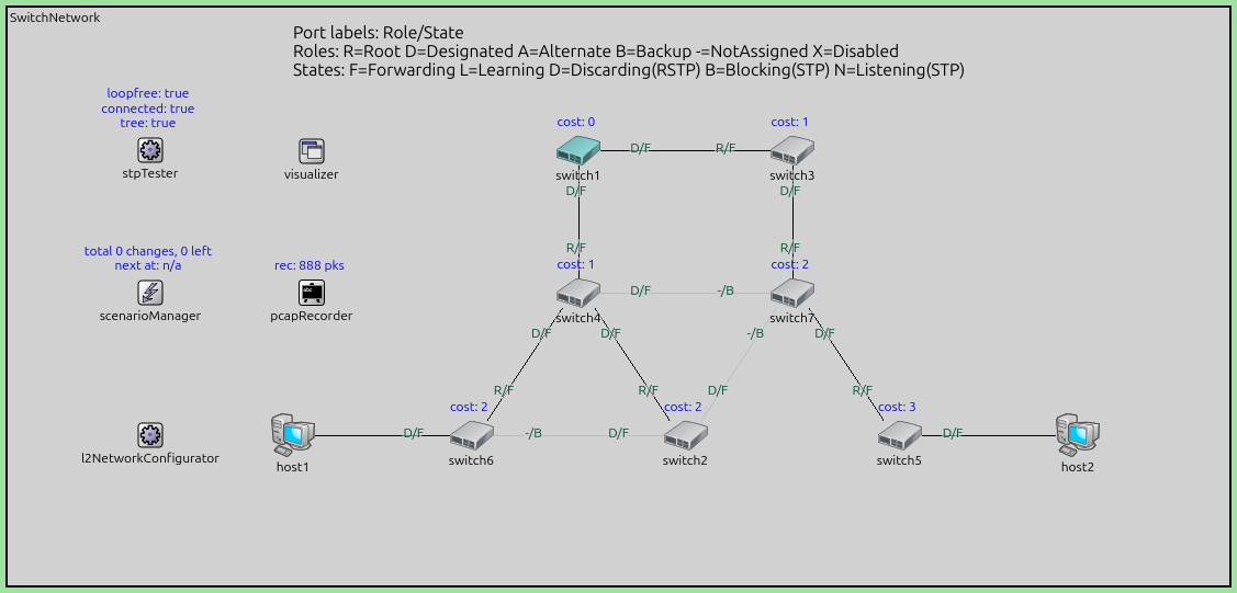
R/F(Root/Forwarding),D/F(Designated/Forwarding),D/N(Designated/Listening),D/L(Designated/Learning),-/B(unassigned/Blocking).Root path cost is displayed above each switch icon:
cost: 0for the root bridge,cost: 19for a switch one hop away over a 100 Mbps link, etc.Link colors: black for Forwarding ports, gray for Blocking/Listening/Learning.
Root bridge is highlighted in cyan with an exclamation mark icon overlay.
Inspecting state variables: double-click on a switch’s
stpsubmodule in Qtenv to inspect internal variables such asbridgeAddress,rootAddress,rootPathCost,isRoot, and per-port data (in the interface table).
Results
After the simulation starts, STP BPDUs (Bridge Protocol Data Units) are exchanged between switches. The following video shows the BPDU traffic during the early phase of convergence:
After approximately 35 s, the spanning tree has converged:
Root bridge:
switch1(lowest MAC addressAAAAAA000001)Blocked ports: the ports creating redundant paths are blocked (shown in gray)
Active tree: a subset of links forms a tree rooted at
switch1
The following video shows the full convergence process in real time. Observe how port states transition from Blocking through Listening and Learning to Forwarding over approximately 36 s:
After convergence (t=60s), host2 begins sending frames to host1 and
receives replies, confirming that the tree provides full connectivity while
remaining loop-free.
Sources:
omnetpp.ini,
StpTutorial.ned
Discussion
Use this page in the GitHub issue tracker for commenting on this tutorial.