Mobility Models
Goals
The positioning and mobility of nodes play a crucial role in many simulation scenarios, especially those that involve wireless communication. INET allows you to add mobility to nodes by using modules that represent different mobility models, such as linear motion or random waypoint. There is a wide variety of mobility models available in INET, and you can even combine them to create complex motion patterns.
This showcase provides a demonstration of some of the elementary mobility models available in INET. The topic of combining multiple mobility models is covered in a separate showcase, Combining Mobility Models.
4.6Overview
Mobility models are mostly used to describe the motion of wireless network nodes. In wireless networks, the signal strength depends on the position and orientation of transmitting and receiving nodes, which in turn determines the success of packet reception. Because of this, position is always relevant, even if the simulation is run without a GUI.
In INET, mobility is added to nodes in the form of modules that represent mobility models. Mobility module types implement the IMobility module interface and are in the inet.mobility package. This showcase presents an example for most of the frequently used mobility models.
Mobility models can be categorized in numerous different ways (see User’s Guide), but here we present them organized in two groups: ones describing proper motion and/or dynamic orientation and ones describing the placement and orientation of stationary nodes.
For the interested reader, the INET User’s Guide contains a more in-depth treatment of mobility models.
The Model
All simulations use the BasicMobilityShowcase network. The size of the scene is 400x400x0 meters. It contains a configurable number of hosts and an IntegratedCanvasVisualizer module to visualize aspects of mobility. The following image shows the layout of the network:

The General configuration in the omnetpp.ini file contains some configuration
keys common to all example simulations:
**.networkConfiguratorModule = ""

*.visualizer.mobilityVisualizer.displayMobility = true # master switch
*.visualizer.mobilityVisualizer.displayPositions = true
*.visualizer.mobilityVisualizer.displayOrientations = true
*.visualizer.mobilityVisualizer.displayVelocities = true
*.visualizer.mobilityVisualizer.displayMovementTrails = true

**.constraintAreaMinX = 0m
**.constraintAreaMaxX = 400m
**.constraintAreaMinY = 0m
**.constraintAreaMaxY = 400m
**.constraintAreaMinZ = 0m
**.constraintAreaMaxZ = 0m
All visualization features of MobilityVisualizer are turned on, and the constraint areas of all mobility modules are set to match the size of the scene. All nodes will move in the XY plane, so the Z coordinate is always set to 0.
The model does not need a network configurator module because there is no communication between the hosts, so we set the configurator module path in the hosts to the empty string.
Motion
This section covers mobility models that define motion. Such models in INET include AnsimMobility, BonnMotionMobility, ChiangMobility, CircleMobility, FacingMobility, GaussMarkovMobility, LinearMobility, MassMobility, Ns2MotionMobility, RandomWaypointMobility, RectangleMobility, TractorMobility, TurtleMobility, and VehicleMobility.
Some of these mobility models are introduced by the following example simulations.
LinearMobility
The LinearMobility module describes linear motion with a constant speed.
As such, it has parameters for speed and starting heading.
The model also has parameters for initial positioning (initialX,
initialY, initialZ), which, by default, are random
values inside the constraint area.
The configuration in omnetpp.ini is the following:
*.host[*].mobility.typename = "LinearMobility"
**.mobility.speed = 40mps
We leave the initialMovementHeading parameter on its default value,
which is a random value.
The following video shows the motion of the nodes:
The video shows that the seven hosts are placed randomly on the scene with a random starting angle. They all move along a straight line with a constant speed. They also bounce back from the boundaries of the constraint area when they reach it.
CircleMobility
The CircleMobility module describes circular motion around a center. This example uses two hosts orbiting the same center (the center of the scene) with different radii, directions, and speeds:
*.host[*].mobility.typename = "CircleMobility"

*.host[0].mobility.cx = 200m
*.host[0].mobility.cy = 200m
*.host[0].mobility.r = 80m
*.host[0].mobility.speed = 60mps
*.host[0].mobility.startAngle = 90deg

*.host[1].mobility.cx = 200m
*.host[1].mobility.cy = 200m
*.host[1].mobility.r = 150m
*.host[1].mobility.speed = -80mps
*.host[1].mobility.startAngle = 270deg
You can see the result of the configuration in the following video:
TurtleMobility
TurtleMobility is a programmable mobility model, where the “program” is provided in the form of an XML script. The script can contain commands that set the position and speed, turn by some specified angle, travel a certain distance, etc. These motion elements can be used as building blocks for describing various motion patterns.
The mobility model’s only ini parameter is turtleScript, which
specifies the XML file to use:
*.host[*].mobility.typename = "TurtleMobility"

*.host[0].mobility.turtleScript = xmldoc("config.xml")
*.host[1].mobility.turtleScript = xmldoc("config2.xml")
The simulation contains two hosts, of which host[0] moves along a perfect hexagon. Here you
can see the XML script for host[0]:
<movement>
    <!-- draw a hexagon -->
    <set speed="30" x="143" y="100"/>
    <repeat>
        <forward d="100"/>
        <turn angle="60"/>
    </repeat>
</movement>
The flexibility of TurtleMobility allows the implementation of
the functionality of some of the other mobility models.
As such, host[1]’s XML script describes another mobility model, MassMobility.
This is a mobility model describing random motion. The node is assumed to have mass, and so it
cannot turn abruptly. This kind of motion is achieved by allowing only
small time intervals for forward motion and small turning angles:
<movement>
    <!-- MassMobility -->
    <repeat>
        <set speed="uniform(35,45)"/>
        <turn angle="uniform(-30,30)"/>
        <forward t="uniform(0.1,1)"/>
    </repeat>
</movement>
It looks like the following when the simulation is run:
GaussMarkovMobility
GaussMarkovMobility model uses the Gauss-Markov mobility model
that involves random elements when describing the motion.
It has an alpha parameter which can run from 0
(totally random motion) to 1 (deterministic linear motion), with the
default value of 0.5.
The random variable has a mean of 0, and its variance can be set by
the speedStdDev and angleStdDev parameters.
The margin parameter adds a margin to the boundaries of the constraint
area, so that the mobility bounces back before reaching it.
Here is the configuration in omnetpp.ini:
*.host[*].mobility.typename = "GaussMarkovMobility"

**.mobility.speed = 40mps

**.mobility.margin = 0m
**.mobility.speedStdDev = 0.5mps
**.mobility.angleStdDev = 0.5rad
**.mobility.alpha = 0
The mobility module is set to totally random motion, with a variance of 0.5mps and 0.5rad for the speed and the angle, respectively.
The following video shows the resulting random motion:
FacingMobility
FacingMobility only affects orientation: it sets the orientation
of the mobility module to face towards another mobility module.
More precisely, the orientation is set to point from a source mobility module
to a target mobility module. Both can be selected by the sourceMobility
and targetMobility parameters.
By default, the sourceMobility parameter is the mobility module
itself. The targetMobility parameter has no default value.
For example, if host3’s sourceMobility parameter is set to host1’s
mobility module, the targetMobility parameter to host2’s mobility module,
the orientation of host3 points in the direction of the
host1-host2 vector:
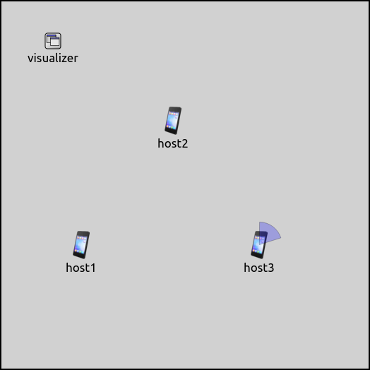
Note that this screenshot is not from the example simulation; it is just for illustration.
The example simulation contains seven hosts.
host[0] is configured to move around using LinearMobility, while the rest of the nodes
are configured to face host[0] using FacingMobility:
*.host[1..6].mobility.typename = "FacingMobility"
*.host[1..6].mobility.targetMobility = "^.^.host[0].mobility"
The following video shows how all of the nodes are facing host[0] as it moves:
BonnMotionMobility
The BonnMotionMobility mobility model is a trace-based mobility model, which means that node trajectories come from a pre-recorded trace file. The BonnMotionMobility uses the native file format of the BonnMotion simulation tool. The file is a plain text file, where every line describes the motion of one host.
A line consists of either (t, x, y) triplets or (t, x, y, z) quadruples. One tuple means
that the given node gets to the point (x,y,[z]) at the time t.
The is3D boolean parameter controls whether lines are interpreted as consisting
of triplets (2D) or quadruples (3D). Here you can see the configuration in the ini file:
**.host[*].mobility.typename = "BonnMotionMobility"
**.host[*].mobility.traceFile = "bonnmotion.movements"
**.host[*].mobility.is3D = false
**.host[*].mobility.nodeId = -1
The nodeId parameter selects the line in the trace file for the given mobility module.
The value -1 gets substituted for the parent module’s index.
The bonnmotion.movements file contains the trace that we want the nodes to follow:
1 100 100 3 175 100 6 175 250 7 150 275 10 100 350
1 300 100 3 225 100 6 225 250 7 250 275 10 300 350
If we take host[0] for example, it gets the first line of the file. It stays at the position
(100,100) for 1 second, then moves to the point (175,100) on a straight line and gets there at
t=3s, etc.
The movement of the nodes looks like the following when the simulation is run:
Stationary Placement
The following mobility models define only the stationary position and initial orientation: StaticGridMobility, StaticConcentricMobility, StaticLinearMobility, StationaryMobility.
StaticGridMobility
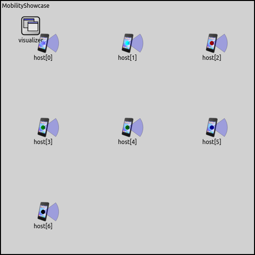
The example simulation is run with seven hosts.
StaticGridMobility positions all nodes in a rectangular grid. It has
parameters for setting the properties of the grid, such as a margin, the
number of row and columns, and the separation between rows and columns.
By default, the grid has the same aspect ratio as the available space
(constraint area by default). The numHosts parameter must be set in
all mobility modules of the group.
The configuration in omnetpp.ini is the following:
*.*host[*].mobility.typename = "StaticGridMobility"
*.*host[*].mobility.numHosts = 7
We specify only the numHosts parameter; the other parameters of the
mobility are left at their defaults. Thus the layout conforms to the
available space:
StationaryMobility
The StationaryMobility model only sets position. It has initialX, initialY, initialZ
and initFromDisplayString parameters. By default, the initFromDisplayString parameter is
true, and the initial coordinate parameters select a random value inside the constraint
area. Additionally, there are parameters to set the initial heading, elevation, and bank
(i.e., orientation in 3D), all zero by default. Note that StationaryMobility is the
default mobility model in WirelessHost and derivatives.
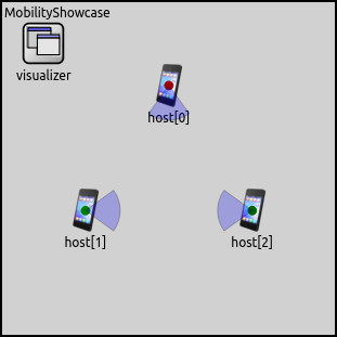
The configuration for the example simulation in omnetpp.ini is the following:
*.numHosts = 3

*.*host[*].mobility.typename = "StationaryMobility"

*.host[*].mobility.initFromDisplayString = false

*.host[0].mobility.initialX = 200m
*.host[0].mobility.initialY = 100m
*.host[0].mobility.initialZ = 0m
*.host[0].mobility.initialHeading = 90deg
*.host[1].mobility.initialX = 100m
*.host[1].mobility.initialY = 250m
*.host[1].mobility.initialZ = 0m
*.host[2].mobility.initialX = 300m
*.host[2].mobility.initialY = 250m
*.host[2].mobility.initialZ = 0m
*.host[2].mobility.initialHeading = 180deg
The configuration just sets the mobility type. Here is what it looks like when the simulation is run:
Sources: omnetpp.ini, BasicMobilityShowcase.ned
Try It Yourself
If you already have INET and OMNeT++ installed, start the IDE by typing
omnetpp, import the INET project into the IDE, then navigate to the
inet/showcases/mobility/basic folder in the Project Explorer. There, you can view
and edit the showcase files, run simulations, and analyze results.
Otherwise, there is an easy way to install INET and OMNeT++ using opp_env, and run the simulation interactively.
Ensure that opp_env is installed on your system, then execute:
$ opp_env run inet-4.6 --init -w inet-workspace --install --build-modes=release --chdir \
   -c 'cd inet-4.6.*/showcases/mobility/basic && inet'
This command creates an inet-workspace directory, installs the appropriate
versions of INET and OMNeT++ within it, and launches the inet command in the
showcase directory for interactive simulation.
Alternatively, for a more hands-on experience, you can first set up the workspace and then open an interactive shell:
$ opp_env install --init -w inet-workspace --build-modes=release inet-4.6
$ cd inet-workspace
$ opp_env shell
Inside the shell, start the IDE by typing omnetpp, import the INET project,
then start exploring.
Discussion
Use this page in the GitHub issue tracker for commenting on this showcase.